Realistic 12-655 Tech Page
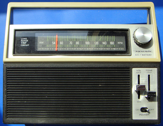
This page is designed to give you quick, accurate technical information about the Realistic 12-655 AM portable radio. Sold in the middle 1970's, this radio proved that Radio Shack can indeed manufacture an AM radio with real DX capability. All that they usually lack is the desire to do so.
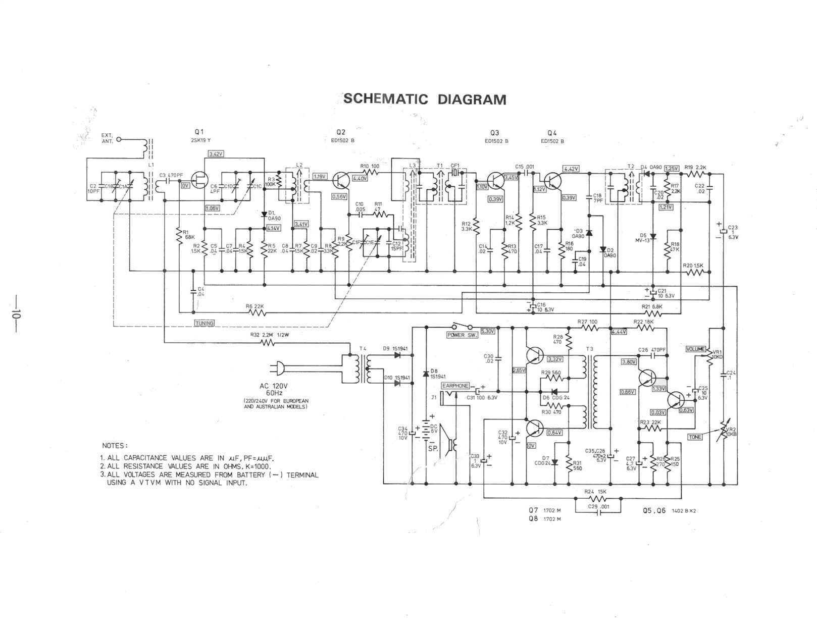
The 12-655 employs a tuned RF design, with an IF amplifier that contains one ceramic filter (integrated in the first IF can), and two LC IF filters. With no modifications, the radio is capable of very good sensitivity and selectivity, but the limited number of IF stages makes it a bit prone to overload by nearby local stations. There is a modification to improve this - and I cover it below.
My 12-655 has been heavily used, and even more heavily modified over the years. A really astute owner might notice I had to replace the power switch with a toggle type - the original slide switch wore out long ago. Other repairs/ mods that I made will be covered as I go along.
Besides the aforementioned power switch, I also had to replace the combination ceramic filter / LC first IF can. I bought extras from Radio Shack at the time, and it appears that was a good thing to do. I discovered that if light and/or aire hits the ceramic filter, it quits working. So leave it in the can!
Another annoyance is the mechanical layout of the interior. It makes it almost impossible to install a better speaker:

The speaker is located right below the tuning pulley, and anything much thicker or having a bigger magnet than the stock speaker would be very hard to install. This radio would be a prime candidate for repackaging into another case.
You might notice that I also had to replace the original power transformer, which overheated and almost melted the case. I have had no more problems.

The layout of the PC board is open and easy to service. Unfortunately, there is no silkscreen to aid in component identification. The RF section is to the left, IF center, and audio to the right. The tuning capacitor is oversized as these plastic PC board transistor radio tuing capacitors go, and it has no integral trim caps. They are located on the PC board, and their location near the associated coils make identification during alignment a snap! For those who need extra help, the coils are color coded:
I will leave alignment procedure up to you - the standard caps high coils low works well.
This radio is a good candidate for covering the expanded band - I had to open the oscillator trim cap almost all of the way open, though, to reach 1700 kHz. Dial calibration is hardly affected until you reach 1200 kHz. I haven't bothered with a different dial legend, I just memorize where the stations are and tune by context (what stations are nearby).
I got a little ahead of myself. Here are abridged disassembly instructions:


This is as much disassembly as I have done, I have not removed the board from the chassis.
As I stated above, this radio "out of the box" has good selectivity. But it is also prone to overload from nearby strong locals - something that is very characteristic of Radio Shack radios. This modification fixes the problem.
The first step in doing the narrow IF filter modification is to move the tuning pulley out of the way. I use my old standby - duct tape - to hold it firmly in place while I work on the board. The dial string goes slack, so I had be a bit careful, but I had no problems with the dial cord when I replaced the pully.
Sorry to be a bit vague here, but I did the initial part of this work 35 years ago and have forgotten the original circuit configuration of the board. When I brought the radio back out of storage, it was non-functional with too many ceramic filters installed. I reverted back to bypassing two pads shown in the red circle with a capacitor, and the radio worked normally. It is my believe that these pads may have been a trace on the board originally, but I can't remember.

Next, I removed the capacitor and replaced it with a three element, stagger-tuned 455 kHz ceramic filter salvaged from a junked wireless mouse. Sorry the detail isn't better in the picture, but I did have to install the body of the ceramic filter a little offset from the two pads, and used scrap component leads to angle up to the pads. The three ground connections come out the bottom of the ceramic filter, and the input and output are on the other edge.

The dial string barely clears the body of the ceramic filter, but doesn't touch it.
All I can say is - fantastic! As I tune across the dial, not only is the slop-over from strong nearby local signals completely eliminated, but selectivity and sensitivity are amazing across the whole band. It has the characteristic "swoosh" you get from narrow band radios as you near a station. Distant first adjacents in my listening location are now easily heard by simply nulling local offenders - to a much greater degree than any other radio I own. Even distant KONO on 860 from San Antonio can be isolated and received virtually interference free from local KEYH 850. KEYH is a Spanish language station, and NOT a good neighbor, employing a lot of high frequency sound effects that usually strongly affect KONO. These are all but eliminated!
Sensitivity also is way better, making this the most sensitive AM portable I own by a large margin. Lower frequency 5kW regionals up to 200 miles away sound like locals with no static. 590 in the Houston area is a mixture of KLBJ Austin and much more distant XEFD from Mexico. After this upgrade, distant XEFD can be made to come in almost clear when KLBJ is nulled. There are numerous other locations where faint signals from Mexico are now clearly audible, such as XEMU 580, XEGH 620. KRLD 1080 can be clearly heard next to powerful local KNTH. It is the same situation with distant first adjacents across the band, I haven't even begun to log all of them. There are distant signals audible on almost every frequency that is blank on other radios I own - 830, 840, etc. This is without a loop helping, either. Just the internal ferrite bar, and I do have larger ones that will fit easily in the case! One benchmark I use to test is WWL New Orleans. Pops right in on the modified 12-655, weak but listenable. This is the only radio I own which will do it unassisted this far inland.
The verdict? Radio Shack made a real winner - if you can possible get one at a flea market or eBay, do it! Even without the mod, it is a remarkable little portable. If you do the narrow filter mod - this one is one hot DX machine that I would compare favorably to any other radio you can propose, even very expensive communications receivers.
Click the small icon to get the full size page: