CCrane Radio EP Technical Page
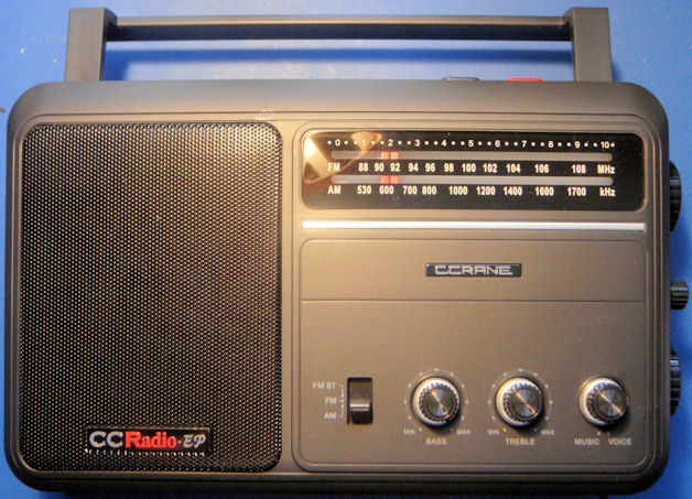
A recently introduced radio, the CCrane Radio EP, has been touted as a replacement for the legendary GE Superadio series. But what is the reality? A claim like that is extraordinary, and extraordinary claims demand extraordinary evidence.
Out of the box, the radio did not disappoint. I am a skeptic by nature, fooled by years of marketing hype and suspicious of every lofty claim. In every way, it excels at AM reception - the selling point of the Superadio series. While I cannot yet verify FM performance, it is a solid performer easily bringing in the entire group of local and near fringe stations near Houston. Some of the very weak stations in the non-comm part of the band are easily receivable. But - the dial calibration was way off on the high end of the band. This radio needed alignment - an excuse to get inside and see what makes this radio so good.
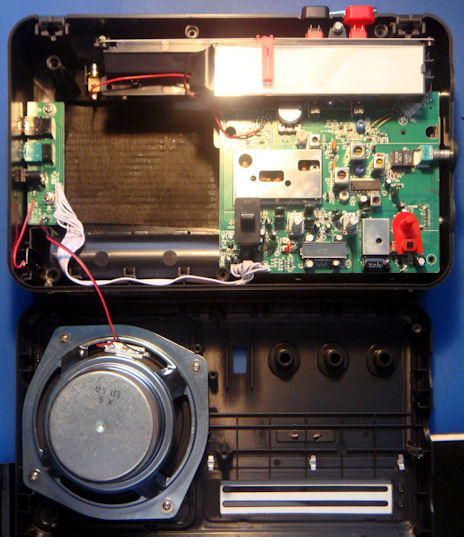
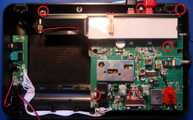
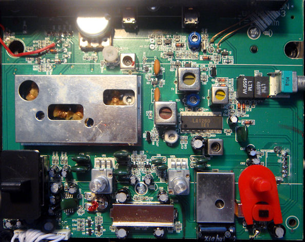
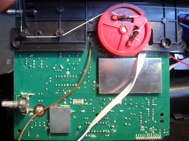
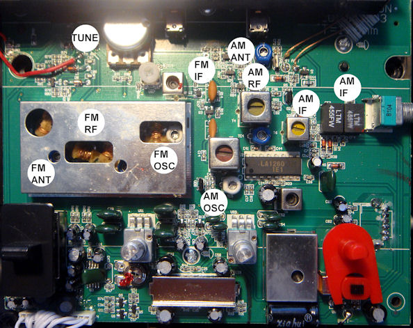
The circuit board view reveals much about the design. The RF design is based on an LA1260 integrated circuit, one of the many excellent Sanyo "radio on a chip" IC's. This radio takes the basic idea of simple implementation in a single IC, and adds tuned RF stages and good IF strips to the design, making a really excellent radio.
The FM front end is shielded under a can at the left, but is obviously tuned RF, and there is easy access to alignment points without removing the cover. AM Oscillator, RF, and Antenna stages are also clearly visible.
IF for the FM is composed of one can and two ceramic filters. The ceramic filters are 280 kHz Murata types - a real area of easy modification. Since this radio has an FM stereo setting, one can only assume that a MPX decoder is on the board, so it would be important not to go below 150 kHz bandwidth on ceramic filters. The IF for the AM is similar - one can and two ceramic filters. The ceramic filters are each a three element stagger tuned variety, one that I am familiar with from salvaging wireless mice, and one with a slightly different part number.
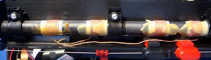
The picture below shows the "twin coil" ferrite bar antenna.
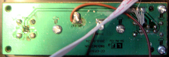
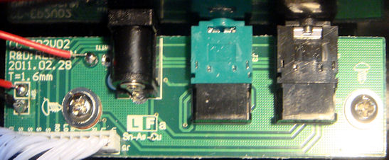
There are smaller auxiliary PC boards as discussed above:
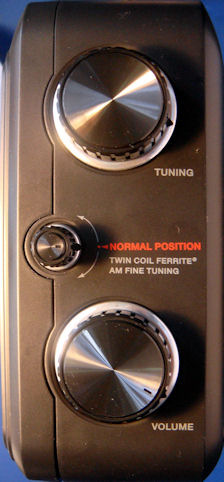
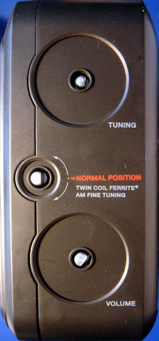
I've only been inside once, and this is from memory. Please correct me and add other notations if you want! I had to copy the front of the radio and tape a dial legend over the white light panel - similar to what I have to do with an SR-3 in order to do the alignment.