Ceramic filters are electronic components used as the bandpass element for Intermediate Frequency (IF) amplifier stages of an FM radio. Ceramic filters can also be employed for other purposes such as AM and TV IF stages, but this page concentrates on their use in FM tuners and receivers. The general discussion here applies to these other applications as well.
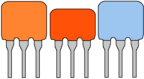
Ceramic filters are available from many manufacturers, but usually share several characteristics in common. They are three lead rectangular devices that resemble ceramic capacitors except for the three leads. The leads are on 1/10 inch spacing. They can be various colors (although brown is the most common) and heights, although the middle picture below depicts a Toko filter which is usually red and lower profile.

The three pins from left to right are input, ground, and output. The devices are polarized so make sure that you get the input pin connect.
The electrical function that ceramic filters perform is that of a passive bandpass filter centered on 10.7 MHz. A bandpass filter passes its center frequency, while rejecting frequencies to each side of the center. The quality, or "Q" factor of a bandpass filter is a measure of how sharply it rejects the frequencies to each side of the center frequency. The Q of FM ceramic filters is not specified directly, instead it is stated as the bandwidth at which the filter has rolled off by 3 dB above and below the center frequency. For a "150 kHz" ceramic filter, then, the signal would be rolled off 3 dB at 10.625 MHz and 10.775 MHz. This is shown in the picture below:
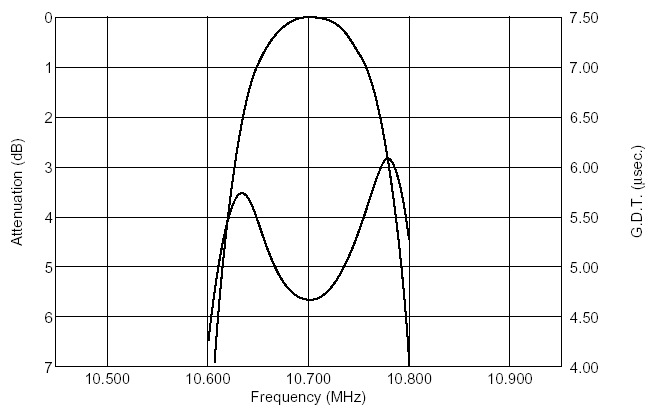
This figure needs a number of comments:
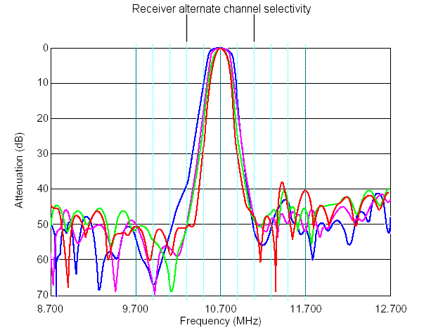
The real story on tuner selectivity is better shown by a graph that is wider in both frequency and amplitude:
If you modify tuners, you will need some method of testing ceramic filters. The figure below is taken from a Murata data sheet (I have corrected a mistake where they swapped the output and ground pin numbers):
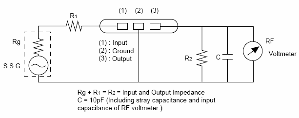
While this method will work, I am fortunate to have access to an Agilent 8753E, which allows me to get a good visualization of the filter characteristics. A little modification to the diagram above is needed, however. Instead of the AC voltmeter, I connected the high impedance input of a non-inverting op amp stage to the filter output:
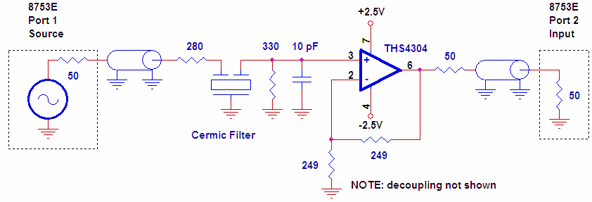
This allowed me to match the 50 ohm input impedance of the network analyzer to the 300 Ohm impedance of the filter. A THS4304 has a gain / bandwidth product of 3 GHz, so its effect on the characteristics of the filter is negligible. The gain of the op amp stage is 2 at the amplifier output, but the effect of matching / terminating resistors results in an overall gain of 1 at the network analyzer input. Therefore, this circuit can be used to measure the insertion loss of the filter.
A network analyzer plot of a good filter is shown on the red trace below:
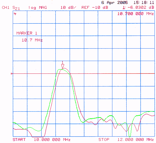
Occasionally, a filter showed a response that was not symmetrical, as shown in the green trace. Perhaps I am obsessing a little bit about the shape of the bandpass characteristic. Ideally, it would be perfectly flat across the top, then have a perfectly vertical dropoff to zero on each side of the pass band. As noted above, this is not the case. In the real world, you at least would want the passband to do the same thing on either side of the center frequency. This way, the frequency deviation would be symmetrical on each side as the station deviates +/-75 kHz. The nature of frequency modulation makes it immune to amplitude variations in ideal realm, but in the real world amplitude variations will affect the audio to a degree. So I flag these devices as undesirable, and do not use them.
The next aspect of filter response to consider is center frequency. For those of you who have digital tuning, you are stuck with having to find filters that are as close to 10.7 MHz as possible. This is because the tuning voltage will set up the varactor diodes in the front end of the receiver for an exact 10.7 IF. If you are really ambitious, you might see if you can intercept the tuning voltage before it goes to the front end and add a trimming circuit. This will have two benefits:
The red trace above shows a nice, symmetrical response that is centered slightly higher than 10.7 MHz in frequency. As long as the other filters in the IF stage are matched to this center frequency, you will be fine - especially if you have an analog tuner. The slightly high IF frequency will result in a miniscule difference in dial calibration - and that is all.
In order to really understand what is going on with the filter near its center frequency, it is necessary to increase the resolution near the center frequency:
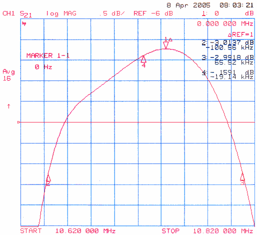
This figure shows a key fallacy of the AC voltmeter method of test selecting filters. This filter is not very symmetrical. The vertical scale of the diagram is 0.5 dB, and the passband is skewed to the right. The AC voltmeter method of finding the peak will yield a center frequency of about 10.745 MHz. If this filter is used to match other 10.745 MHz ceramic filters in an IF stage, a portion of its skewed response will amplify unwanted adjacent stations. Marker 2 shows that the -3 dB point on the low end of the passband is 100 kHz from the amplitude peak, while marker 3 shows the upper end of the passband is only 66 kHz from the amplitude peak.
Rather than characterize this filter based on the peak from the AC voltmeter, I think it should be characterized by its -3 dB points as shown here:
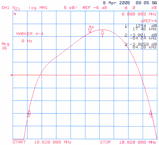
Here, all references have been changed from the peak (marker 1) to the center frequency (marker 4), which is 17 kHz lower. Doing this places the filter within spec for the center frequency (about 10.727 MHz). The -3 dB points are +/-84 kHz, which means this filter is a 168 kHz wide filter. That is within spec for a 150 kHz +/- 30 kHz bandwidth filter. Again - I would mark this filter as unacceptable for use in high end tuners, but it does illustrate several aspects of filter performance.
The following manufacturers make ceramic filters. Of these - two are commonly available to hobbyists through Digi-Key - Murata and Toko
Manufacturers can sometimes be identified by color:
Murata is the most common manufacturer, and is very easy to get from Digi-Key. There are two tables associated with Murata - a legacy part number table and a new part number table. The legacy part number table is included because there are a tremendous number of older legacy filters still available through distribution and in tuners - manufactured before a part number standardization initiative in 2001. The tables are sorted by typical 20 dB bandwidth. The more desirable filters for broadband use are near the top, and the more desirable filters for DX use are near the bottom of each table.
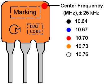
NOTE: Many manufacturers follow the center frequency dot convention. Murata uses the location of the dot to differentiate part markings, as described in the table below.
| Murata Part Number | 3 dB bandwidth | 20 dB bandwidth max (typ) | Insertion Loss max (typ) | Part Marking |
|---|---|---|---|---|
| SFE10.7MA21 | 400 | 950 (750) | (3) | |
| SFE10.7MA19 | 350 | 950 (750) | (3) | E10.7A center dot |
| SFT10.7MA5 | 280 | 700 (630) | (6) | T10.7A |
| SFE10.7MX-A | 250 | 670 (620) | 12 (10) | |
| SFE10.7MA20-A | 330 | 680 (615) | (4) | E10.7A center dot |
| SFE10.7ML-A | 280 | 700 (610) | 9 (7) | E10.7L |
| SFT10.7MS2 | 230 | 650 (580) | (6) | T10.7S left dot |
| SFE10.7MX2-A | 220 | 610 (560) | 12.5 (10.5) | E10.7X |
| SFE10.7MP3-A | 250 | 650 (550) | 10 (8) | E10.7P |
| SFE10.7MA5C10-A | 280 | 650 (540) | (3.0) | 10.7AC |
| SFE10.7MA5-A | 280 | 650 (520) | 6 (4) | E10.7A left dot |
| SFE10.7MA8-A | 280 | 650 (520) | 6 (4) | E10.7A left and center dot |
| SFE10.7MA5B10-A | 280 | 650 | (3.0) | E10.7AB |
| SFE10.7MM-A | 230 | 600 (510) | 11 (9) | E10.7M |
| SFT10.7MS3 | 180 | 550 (500) | (8) | T10.7 right dot |
| SFE10.7MA5A10-A | 280 | 590 (480) | (2.5) | E10.7AA left dot |
| SFE10.7MS2C10-A | 230 | 570 (470) | (3.0) | 10.7SC left dot |
| SFE10.7MZ1-A | 180 | 530 (460) | 14 (12.3) | E10.7Z right dot |
| SFE10.7MS2G-A | 230 | 600 (420) | 7 (4.5) | E10.7S left dot |
| SFE10.7MS2-A | 230 | 570 (420) | 6 (4) | E10.7S left dot |
| SFE10.7MZ2-A | 150 | 500 (420) | 14 (12.6) | E10.7Z left dot |
| SFE10.7MS2B10-A | 230 | 570 | (3.0) | E10.7SB left dot |
| SFE10.7MS2A10-A | 230 | 520 (410) | (3.0) | E10.7SA left dot |
| SFE10.7MS3-A | 180 | 520 (380) | 7 (4.5) | E10.7S right dot |
| SFE10.7MS3G-A | 180 | 520 (380) | 7 (5) | E10.7S right dot |
| SFE10.7MS3B10-A | 180 | 520 | (5.0) | E10.7SB right dot |
| SFE10.7MS3A10-A | 180 | 470 (370) | (3.5) | E10.7SA right dot |
| SFE10.7MS3C10-A | 180 | 470 (360) | (3.5) | 10.7SC right dot |
| SFE10.7MJA10-A | 150 | 360 (300) | (4.5) | E10.7JA |
| SFE10.7MJC10-A | 150 | 360 (300) | (4.5) | 10.7JC |
| SFE10.7MHC10-A | 110 | 350 (260) | (7.0) | 10.7HC |
| SFE10.7MHY-A | 110 | 350 (260) | (7) | E10.7HY right dot |
| Murata Part Number | 3 dB bandwidth | 20 dB bandwidth max | Insertion Loss max (typ) | Digi-Key Part Number |
|---|---|---|---|---|
| SFELA10M7DF00-B0 | 350 | 950 | (3.0) | 490-1233-ND |
| SFTLA10M7FA00-B0 | 280 | 700 | (6.0) | |
| SFELA10M7FALL-B0 | 280 | 700 | (7.0) | |
| SFELA10M7EA00-B0 | 330 | 680 | (4.0) | 490-1238-ND |
| SFELA10M7GAXX-B0 | 250 | 670 | 12.0 | |
| SFELA10M7FA00-B0 | 280 | 650 | (4.0) | 490-1237-ND |
| SFELB10M7FA00-B0 | 280 | 650 | (3.0) | |
| SFELA10M7FAB0-B0 | 280 | 650 | (3.0) | |
| SFELA10M7FA0G-B0 | 280 | 650 | (4.0) | |
| SFTLA10M7GA00-B0 | 230 | 650 | (6.0) | |
| SFELA10M7GALP03-B0 | 250 | 650 | 10.0 | |
| SFELA10M7GAXA-B0 | 220 | 610 | 12.5 | |
| SFELA10M7GA0G-B0 | 230 | 600 | 7.0 | |
| SFELA10M7GALM-B0 | 230 | 600 | (9.0) | |
| SFELA10M7FAA0-B0 | 280 | 590 | (2.5) | |
| SFELA10M7GA00-B0 | 230 | 570 | (4.0) | 490-1236-ND |
| SFELB10M7GA00-B0 | 230 | 570 | (3.0) | |
| SFELA10M7GAB0-B0 | 230 | 570 | (3.0) | |
| SFTLA10M7HA00-B0 | 180 | 550 | (5.5) | |
| SFELA10M7HAXD-B0 | 180 | 530 | 14.0 | |
| SFELA10M7GAA0-B0 | 230 | 520 | (3.0) | |
| SFELA10M7HA00-B0 | 180 | 520 | 7.0 | 490-1234-ND |
| SFELA10M7HAB0-B0 | 180 | 520 | (5.0) | |
| SFELA10M7HA0G-B0 | 180 | 520 | 7.0 | |
| SFELA10M7JAXE-B0 | 150 | 500 | 14.0 | |
| SFELB10M7HA00-B0 | 180 | 470 | (3.5) | |
| SFELA10M7HAA0-B0 | 180 | 470 | (3.5) | |
| SFELA10M7JAB0-B0 | 150 | 380 | (5.5) | |
| SFELB10M7JA00-B0 | 150 | 360 | (4.5) | |
| SFELA10M7JAA0-B0 | 150 | 360 | (4.5) | 490-1232-ND |
| SFELB10M7KA00-B0 | 110 | 350 | (7.0) | |
| SFELA10M7KAB0-B0 | 110 | 350 | (7.0) | |
| SFELA10M7KAH0-B0 | 110 | 350 | (7.0) |
Toko is another common manufacturer, and is very easy to get from Digi-Key. These filters are generally shorter than Murata, and are easily identified by their red color. Some DX'ers have reported that high-side selectivity is not as good as low side. A look at their data sheets reveals close in response that looks symmetrical, so they have either fixed their process or the high-side rejection problem only shows up on wider plots.
| Toko Part Number | 3 dB bandwidth | 20 dB bandwidth max | Insertion Loss max (typ) | Digi-Key Part Number | Part Marking |
|---|---|---|---|---|---|
| SK107MAN-AE-10 | 380 | 720 | 5.0 | TK2311-ND | SKMAC |
| SK107M0N-AE-10 | 330 | 680 | 6.0 | TK2310-ND | SKM0C |
| SK107M1N-AE-10 | 280 | 650 | 6.0 | TK2304-ND | SKM1C |
| SK107M2N-AE-20 | 230 | 600 | 6.0 | TK2306-ND | SKM2C |
| SK107M3N-AE-20 | 180 | 520 | 7.0 | TK2307-ND | SKM3C |
| SK107M4N-AE-20 | 150 | 400 | 10.0 | TK2308-ND | SKM4C |
| SK107M5N-AE-10 | 110 | 350 | 10.0 | SKM5C | |
| SK107M0N-AE-10X | 330 | 680 | (2.5) | SKM0C | |
| SK107M1N-AE-10X | 280 | 650 | (2.5) | SKM1C | |
| SK107M2N-AE-20X | 230 | 600 | (3.0) | SKM2C | |
| SK107M3N-AE-20X | 180 | 520 | (3.5) | SKM3C | |
| SK107M4N-AE-20X | 150 | 400 | (5.5) | SKM4C | |
| SK107M5N-AE-10X | 110 | 350 | (6.0) | SKM5C | |
| SK107M1N-AE-10G | 280 | 650 | 6.0 | SKM1C | |
| SK107M2N-AE-20G | 230 | 600 | 6.0 | SKM2C | |
| SK107M3N-AE-20G | 180 | 520 | 7.0 | SKM3C | |
| SK107M4N-AE-20G | 150 | 400 | 10.0 | SKM4C | |
| SK107M5N-AE-10G | 110 | 350 | 10.0 | SKM5C |
A number of Chinese manufacturers have cooperated in adopting a standardized part numbering system for FM ceramic filters. Several provide filters in standard and low profile sizes. Often times, the low profile products are also low loss / better selectivity. Sort of an attempt to put all of the "good" characteristics into a premium "A10" part number. The following table is compiled from a list of typical specifications from these manufacturers. It may be very difficult to identify the exact manufacturer of a ceramic filter by the part marking - as these are commodity items. The primary value of this table is to summarize device characteristics from the part marking. While SNR is not a Chinese manufacturer, it still adheres to the Chinese numbering scheme.
Some of these manufacturers no longer make ceramic filters, but I have included them in the list because they did at one time and their products are still found in many FM receivers.
| Part Number | 3 dB bandwidth | 20 dB bandwidth max (typ) | Insertion Loss max (typ) | high/low profile | Part Marking | Made by: |
|---|---|---|---|---|---|---|
| LT10.7MA19 | 350 | 950 | 3 | H | LCE,S,T,JK | |
| LT10.7MA20 | 330 | 680 | 4 | H | LCE,S,T | |
| LT10.7MA5 | 280 | 650 | 6.0 | H | L10.7A | HKC,L,LCE,S,SNR,T,JK |
| LT10.7MS2 | 230 | 600 | 6.0 | H | HKC,L,LCE,S,SNR,T,JK | |
| LT10.7MS3 | 180 | 520 | 7.0 | H | HKC,L,LCE,S,SNR,T,JK | |
| LT10.7MJ | 150 | 400 | 10.0 | H | L10.7J | HKC,L,LCE,S,SNR,T,JK |
| LT10.7MA5A10 | 280 | 590 (480) | (2.5) | L | L10.7A | HKC,LCE,S,T,JK |
| LT10.7MS2A10 | 230 | 520 (410) | (3.0) | L | HKC,LCE,S,T,JK | |
| LT10.7MS3A10 | 180 | 470 (370) | (3.5) | L | HKC,LCE,S,T,JK | |
| LT10.7MJA10 | 150 | 360 (300) | (4.5) | L | L10.7J | HKC,LCE,S,T,JK |
| LT10.7MHY | 110 | 680 | 7 | H | LCE,T,JK |
Manufacturer legend for table above:
| Hong Kong Crystal: | HKC |
|---|---|
| Languang: | L |
| Shenzhen Luguang: | LCE |
| Shoulder | S |
| SNR | SNR |
| Technical Crystal | TIC |
| Token | T |
| Zhejiang Jiakang | JK |
One manufacturer - Sunny Electric - deviates slightly from the standard, and so they get their own table:
| Part Number | 3 dB bandwidth | 20 dB bandwidth max (typ) | Insertion Loss max (typ) | high/low profile | Part Marking |
|---|---|---|---|---|---|
| SFT10.7MA5 | 280 | 650 | 6.0 | H | FST10.7MA5 |
| SFT10.7MS2 | 230 | 600 | 6.0 | H | FST10.7MS2 |
| SFT10.7MS3 | 180 | 520 | 7.0 | H | FST10.7MS3 |
| SFT10.7MJ | 150 | 400 | 10.0 | H | FST10.7MJ |