The Portable 3 Foot Ribbon Cable Loop

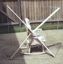
The three foot ribbon cable loop assembled, propped up by a child's rocking chair - it is not self supporting. This is a very "hot" design - excellent "Q" and excellent sensitivity.

The three foot ribbon cable loop dis-assembled, and ready to transport.
Introduction
One idea that has been suggested for constructing a loop is to use ribbon cable, with a winding spacing of 0.050 inch, to consturct the loop. I saw a loop antenna article at one time that
recommended the use of flat ribbon cable, and showed how to make a loop by using the ribbon cable, offset by one pin, on two "D" style connectors, and plugging together to form the loop. I have never
seen that article again, so I suspect it has been removed from the web. So I thought I would resurrect the idea.
This article describes how to construct a loop from ribbon cable. The folding loop article describes a portable loop, but I was not very happy with it. In its folded
position, it was too long to throw into the back of my van to take to my remote test site. It is also heavy, and suffered from a low Q that also plagues my four foot loop.
For that trip to the pool I described in the folding loop article, I need something even better! This time, I will add the requirements that the portable loop be lightweight, and that it will not be
long - like the folding loop in its folded configuration. I also will not test any loop that suffers from low Q.
I looked around for lightweight materials from which to construct a loop. They also have to be non-metallic, which limits the selection quite a bit. Some discarded vertical blinds offered me the
answer. The vertical blind slats are about 84 inches long and 3 1/2 inches wide, and have a slight curve. Individually, they are much too weak to work as a support, but the slight curvature can be
used to create a fairly strong support structure.
Materials
To construct the portable loop, it is necessary to procure the following material:
- Four of the plastic blinds from a discarded set of vertical blinds. They should be the curved plastic type - not metal or wood.
- Construction quality masking tape. I am talking about the type used to tape windows up for hurricanes - which is where I got mine. I used to live in Florida, and had a roll left over. This
tape is about two inches wide, and has good adhesive. That little cheap 3/4 inch stuff sold in art stores will NOT do!
- 12 1/2 feet of ribbon cable - the 25 conductor stuff will do fine, and you can make a couple of loops out of it.
- Small shrink wrap tubing.
- A 9.6 to 365 pF tuning capacitor – the large set of plates in a tuning capacitor salvaged from a junk radio.
Construction
- Cut the four plastic blind pieces to 52 5/8 inches long. Save the discarded pieces.

- Place the blind on the work area, with the curved part "up" in the middle. Place masking tape along both edges of one of the blinds, leaving the sticky part about half exposed.

- Turn the blind with the tape over, and place a second blind over the first, again with the curved part "up" in the middle. Fold the tape up and over both edges.

- Repeat the process with two more plastic blind pieces. You now have the two cross braces for the loop.
- In order for the cross braces to interlock, it will be necessary to cut notches halfway through them in the exact middle, or 26 3/8 inches from the end. The width of the notches is determined by
measuring the thickness of the middle part of the cross brace, but is probably about 3/8 inch. Cut the notches with heavy duty scissors or tin shearers. If regular scissors have to be used, it may
be necessary to separate the two blinds and cut them individually.

- Prepare two one foot sections of blind material from the discarded pieces. Cut two 12 inch by 1 1/4 inch sections from those one foot sections.
- Tape the pieces that you just created onto the braces on the un-notched edge in the middle, one piece on each side. These pieces will compensate for the weakness created by the notch.

- Prepare a 12 foot, 5 inch piece of ribbon cable. It only has to be 7 or 8 conductors wide. Strip and tin each conductor on both ends of the ribbon cable.
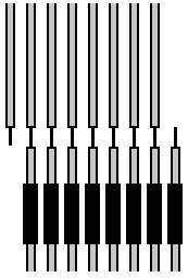
- Make sure there are no "kinks" or twists in the ribbon cable, and match up the two ends so they can be worked with in close proximity. Slide short lengths of shrink wrap onto the wires on one
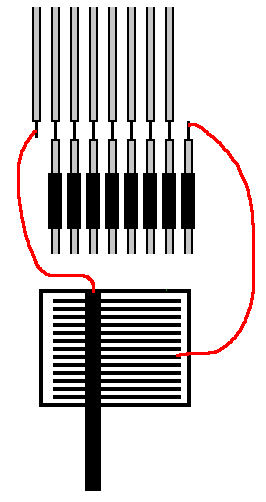
side of the ribbon cable. Solder conductor number TWO of one end to conductor number ONE of the other. Solder conductor number THREE of the first end to conductor number TWO of the other. Continue
this pattern until all but one wire on both ends have been soldered. You should be left with conductor number one of one side loose, and the last conductor of the other side loose.

- Connect conductor 1 of the ribbon cable to the ground terminal of the tuning capacitor, the other end of the other side to the other terminal of the tuning capacitor.

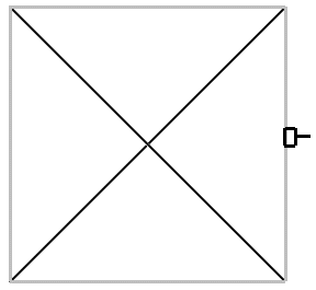
- Slip the two cross braces together for form an "X". This is best done on the floor, as there will be no real strength to the structure yet.

- Slip the ribbon cable over the four edges of the cross braces, slide to the middle. If it is too tight, the edges of the cross braces can be notched. If it is too loose, the ribbon cable will
have to be shortened or small pieces added to the braces by stapling to the ends.

- At this point, the loop structure should be strong enough to erect vertically. It will probably not self support, however, and will need something to lean against (a wooden chair).
- Place a radio in close proximity to the loop, and tune to a weak station near the bottom of the band. Tune the plates of the tuning capacitor until almost closed, and try to optimize the weak
station by tuning the loop. IF the plates are not fully engaged for a station at 540 kHz, there are too many turns on the loop. Re-solder the tuning capacitor to the next conductor in from the end
of the ribbon cable.
- When the tuning capacitor is fully engaged at the low end of the band, double check the tuning at the high end with a weak station. The loop should tune the high end of the band with the tuning
capacitor plates fully disengaged. I was able to compromise between the two ends of the band with 6 conductors in the ribbon cable and a low frequency limit of 550 kHz and a high frequency limit of
1650 kHz. If I wanted fully converage, I would have needed to add a switch to switch a conductor in and out.
- Slide the heat shrink tubing up and fully shrink it to conver the exposed conductors. Tape the tuning capacitor to the ribbon cable, unless you want to use a small plastic box or something to
make it look better.
- A single turn "sense" winding can be made out of an extra conductor in the ribbon cable.
Some notes about the author's loop:
- Q of the loop is EXCELLENT - even at the high end of the band. This dispells the myth that winding spacing has something to do with Q - too narrow and the Q goes down.
- The UMR EMC lab calculator told me that I would need 8 conductors, which is also about the number of conductors in the 1 meter loop projects. This loop only needed
6 conductors, which was disappointing to me, because I thought they had the formula "right". I was able to measure the inductance of my 6 turn loop, and it comes out 200 mH. I have no explanation,
unless the aggregate of RF energy in the Dallas area affected my inductance meter (I can usually see it fluctuate some, especially at night, when measuring one of these loops). I also suspect that
inter-winding capacitance was making up the difference in capacitance and making it resonate in the AM band. Whatever the reasons, it tunes, it works, re-soldering (or taking off turns) is NOT the
pain in the posterior I thought it would be. Hey - once you got a loop that works, you just don't care any more if the calculations were wrong. Just start out with too many turns or conductors, so
you can take them off. Taking them off is a whole lot easier than adding them!!!
- A three foot loop is about the largest loop that can be constructed with this technique. This project started as a five foot loop, but the loop would not self-support, and needed to be
"downsized".
- Test results in the metroplex were about what was expected. A GE Superadio 3 has little improvement, but "cheapies" show tremendous improvement. The antenna was taken to the remote test site
described in the four foot loop antenna article. The results are shown below:
| Internal Antenna Only |
|---|
| Frequency |
Call |
12-732 |
7-2887A |
| 540 |
KDFT |
0 |
0 |
| 610 |
KSVA |
0 |
2 |
| 620 |
KMKI |
3 |
5 |
| 640 |
WWLS |
3 |
4 |
| 650 |
WSM |
0 |
0 |
| 660 |
KSKY |
3 |
4 |
| 770 |
KAAM |
0 |
0 |
| 810 |
WHB |
0 |
0 |
| 820 |
WBAP |
3 |
5 |
| 830 |
WCCO |
0 |
0 |
| 920 |
KENT |
0 |
0 |
| 1020 |
KCKN |
0 |
0 |
| 1110 |
KYKK |
0 |
0 |
| 1150 |
KUHD |
0 |
0 |
| 3 Foot Loop |
|---|
| Frequency |
Call |
12-732 |
7-2887A |
| 540 |
KDFT |
4 |
5 |
| 610 |
KSVA |
2 |
2 |
| 620 |
KMKI |
5 |
6 |
| 640 |
WWLS |
5 |
6 |
| 650 |
WSM |
2 |
2 |
| 660 |
KSKY |
3 |
4 |
| 770 |
KAAM |
5 |
6 |
| 810 |
WHB |
2 |
2 |
| 820 |
WBAP |
5 |
6 |
| 830 |
WCCO |
3 |
3 |
| 920 |
KENT |
5 |
6 |
| 1020 |
KCKN |
5 |
6 |
| 1110 |
KYKK |
6 |
6 |
| 1150 |
KUHD |
2 |
2 |


