The Umbrella Loop
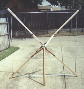
The 5 foot umbrella loop in its open "deployed" configuration.
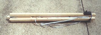
The umbrealla loop folded for transport.
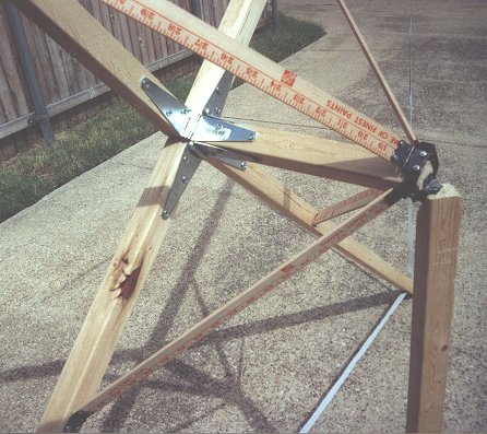
Detail of the folding mechanism of the umbrella loop.
Introduction
Those of you who have read my previous articles know how I have "learned by doing". I started over 30 years ago salvaging loops out of old radios. About 20 years ago I used a simple formula
based on the area and number of turns, and produced a 5 foot planar loop that was good for transatlantic listening - but included no tuning capacitor (it was internal to the radio). I then shelved
the project for 20 years.
I still had my 5 foot planar loop, which was soon adapted to a 4 foot edge wound model with a tuning capacitor. Unfortunately, the wood is actually getting rotted, so it
sits in my father's storage shed 300 miles away. It has such a low Q on the high end of the band that I considered the performance unsatisfactory.
If you don't mind, I will digress a bit before starting this construction article. I have learned a lot of things in the process of building loops. Among other things, I learned that:
- The calculations for loops are not well documented. I still don't have a satisfactory algorithm. The calculators on the front page of this article series get you really
close, but neither one is correct on the high end of the band. I did make a 2 foot edge wound model based on the Joe Carr formula that was
tuned properly from the moment it was constructed. But - for closely spaced loops, only the UMR EMC lab calculator gets close to the right number of turns.
Furthermore, neither they nor the tesla calculation worked for the Terk AM advantage or its Radio Shack clone - both of which are circular loops. The number of turns is incorrect. A correspondent
on an electronics newsgroup referred me to his executable program, which works for small loops but not large. His algorithm is not documented so I don't know where he got his calculations. His
program also works for the closely spaced 3 foot ribbon loop that I made, and for the loop described here. So I suspect that it is correct for closely spaced windings.
Of course it does not work for widely spaced windings. The bottom line here for hobbyists is that it will probably be unavoidable to put too many turns on the windings and remove them until the loop
can be tuned.
- Tuning capacitors are getting hard to find. If you want to build a loop - it would be a good idea to start scouring garage sales for old analog tuned radios. But - I have found that there are
several types of tuning capacitors:
- Extremely old radios and equipment have a type of tuning capacitor with a shaft down the middle, and the plates are on bearings and will not stay in position when the shaft is released. What is
more, the function of the plates is to act as series capacitors between two sets of stationary plates. While it might be possible to use these old devices as tuned elements for a loop, I consider
them unsuitable. I was very excited to find some of these large, multi-section tuning capacitors at my local electronics junk shop. Imagine my disappointment when I discovered their true nature!
- The 9.6 to 365 pF variety. These seem to have gone out of vogue about 30 years ago, replaced by:
- The 500 pF (maximum) variety. These are very nice for loop construction projects, because you have a real chance at getting a loop to tune the whole band with one capacitor. You can easily spot
these, they have more plates than the 365 pF variety. Grab them when you find them!!!
- The 250 pF variety. These are smaller, and have less plates. This is also the type used in the little PCB mount types in portables. The second, smaller set of plates usually does not have
enough capacitance to add up to 365 pF when put in parallel. I picked up three of these at my local electronics shop. Surprisingly - they can be used to make loops that tune the whole AM band! I
will document these loops, constructed on large pieces of styrofoam, in future articles.
- Varactor diodes - I include these because this is where the industry is going. I consider them useless, because one of the nice aspects of loops is that they do not require power to operate. In
theory, it would be pretty simple to use a varactor - just vary the voltage across it to get the desired capacitance.
- Multi-stranded wire seems to give better Q than solid wire. My 500 foot spool of doorbell wire is getting pretty depleted after 4 loop projects, but my latest projects use ribbon cable.
- I am more and more convinced that getting complete coverage of the AM band is one of the hardest tasks facing the loop builder. I have come close with the two foot loop - it tunes from 550 to
1640 kHz. But the umbrella loop described here only tunes 640 to 1700 kHz. I had to include a switch on the windings to cover the whole band. This may not be that bad of a thing - you can
expand the concept to cover shortwave bands.
If you have read my other articles, you know I am driven to make a practical - and portable - loop. I have a scenario of the "swimming pool", where I want music from a distant station with a
minimum of hassle. The loop is impractical if it is large, heavy, delicate, or takes over 30 seconds to deploy. It is also impractical if it is hard to transport or store in its collapsed form. I
wanted to make a really large loop practical to take and use almost anywhere. The folding loop was impractical because it folded to a flat shape that was too long to fit
in a car trunk. The three foot ribbon loop was impractical because it was too delicate and took too long to deploy.
The Umbrella Loop Concept
I saw the answer in an everyday object that just about everybody owns - an umbrella. Like my "ideal" loop, it needs to have a large deployed shape, yet needs to be lightweight enough to carry,
and needs to fold to a compact form that is easy to store. It needs to deploy quickly. It has many characteristics in common with what I want for loop! But - could I make a loop antenna based on
the umbrella design? I cannot use umbrella hardware directly, because it is metal. But - I found a way to use wood instead of metal for the supports, and a minimum of metal used near the center of
the mechanism.
Like the 3 foot ribbon cable loop, this design makes use of ribbon cable. This is almost a necessity, because separate turns would get tangled with this design.
Materials
- Three 8 foot lengths of 2 by 2 lumber. This is usually the smallest size available at the lumber yard. Some warpage is almost inevitable, but does not affect the construction of the loop.
Water sealed lumber will make your loop heavier. I suggest painting the finished pieces as an alternative to water sealed lumber.
- 2 wooden yardsticks. I found these in the checkout lane of Home Depot for 69 cents.
- 4 gate hinges with screws. Often times, gate hinges are not provided with wood screws (see next item).
- 24 1 inch by 1/4 flat head wood screws.
- 9 1 inch furniture hinges.
- 12 4*40 screws, nuts and washers.
- 12 sheetrock screws.
- one 2 inch by 2 inch by 1 inch slide assembly (see text).
- 20 feet of 25 conductor ribbon cable. 25 conductor is the way it is commonly sold.
- a 9.6 to 365 pF tuning capacitor.
- a SPDT switch.
- hookup wire.
- eight plastic push pins (used during construction).
Construction
This is a complex construction project (but not too bad). You need to be careful to do each step carefully. There will be some degree of customization and judgement involved - I will try to
explain the rationale when you need to do this. I will also break this up into sub-assemblies to make it easier to follow.
Constructing the Slide Assembly
The slide assembly is one of the most demanding aspects of this design. I spent many hours thinking about how to design this part of the umbrella loop. If you unfold an umbrella, the slide
assembly is the thing that slides along the center support of the umbrella. I discovered that it needs to be quite strong - as it takes a lot of abuse. This made the selection of material
critical. I searched for something commonly available, strong enough, and a material that can be worked equally. I finally settled on crate strapping metal. There are at least three
types in use. One type is not metal at all, but plastic of some sort. Plastic is completely unsuitable - it is not strong enough. There is also a very flimsy metal type of strapping metal, as
opposed to a thicker metal strapping. It is the thicker metal strapping that you are looking for. It is about 10 mils thick. It should be easy to beg some from somewhere - as it is usually
discarded anyway - and people are anxious to get rid of it because it can cause injuries. I got mine from a computer room retrofit, where it was used to support 6 foot tall racks of equipment. I
suspect that refrigerator and washing machines are also shipped with the same type of strapping metal, so stores that sell them may be a good source.
WARNING Hold the strap metal tightly or secure in a vice for the next step. Don't let it get away from you, it can cut you! If you slice your finger, don't come crying to me about it with
some slimeball lawyer. I warned you!
- Drill two holes in each side of the metal frame to match those in the furniture hinges. Go through both layers of strap metal. It really helps to drill into that scrap piece of 2 by 2, but any
way you do it - it is difficult to hold safely. But - I am a total klutz and I did it, you can too!

- Attached hinges to the metal frame with number 4 hardware. Do yourself a favor and start with the side that wants to unfold. I am not a mechanical engineer and do not have the exact terminology
and length for the bolts - just a bin full of number 4 stuff. Nevertheless - make the bolts the rounded head type, because they will need to slide smoothly up and down a support without tearing up
the wood. You can also use lockwashers if you wish.
You now should have a nice little square metal frame with hinges on it. Next, we will take this assembly and add the "spokes" to it - similar to the spokes that attach to the sliding part of an
umbreall. Only we are going to use yardsticks.
Constructing the Spoke Assembly
Constructing the Frame
- Cut all three of the 8 foot 2 by 2 pieces of lumber in half, to obtain 48 inch sections. You will use 5 of the sections with one in reserve in case of mistakes.
- Cut one of the remaining 48 inch pieces into two pieces, one 34 inches long and the other 14 inches long.
- This is a difficult step, it involves making an angle cut on the end of the 14 inch piece of 2 by 2. You may want to use a mitre box. Start by marking the cut on the end. Draw a 45 degree line
from the middle of one side to the middle of an adjacent side. Next, mark the side of the piece with a triangle extending down about two inches along the sides, starting at the line you drew on the
end. Next, using a coping or other saw designed for fine work, saw off a triangular wedge of the side and end of the piece. The wood to be removed is marked with an "X" on the picture. If you do
not have a mitre box, starting on the edge instead of the end may prove easier.
- Make the same cut as the previous step in the 34 inch piece of 2 by 2.
- Attach a gate hinge to one end of the 48 inch sections. Position it such that when unfolded at a 90 degree angle, the flat part of the free end of the hinge is flush with the end of the wood.
You should pre-drill holes for the screws, as they are large and may split the wood if you try to screw them in without pre-drilling.
- Attach one side of a gate hinge to the upturned face of each of the 4 pieces, such that when the hinge is opened 90 degrees, its flat side is flush with, and parallel with, the end of the 48 inch
piece.
- Lay out four of the 48 inch sections into a cross shape, with 4 ends close together. Take the 14 inch piece of 2 by 2 and position it vertically in the middle of the 4 pieces with the hinges
attached. Place it with the diagonal cut up. Fold over the open end of the hinges until you are ready to attach.
- Attach the open side of the hinges to each side of the vertical piece. The bottom of the 14 inch piece should extend to the floor, and flush with the bottom of the 4 48 inch pieces of 2 by 2.
Again - pre-drilling the holes for gate hinge screws is mandatory. Also - the physical arrangement of screws should prevent interference on all but the top screw. It is a good idea to pre-drill the
top holes slightly diagonal so the screws will clear each other.

- Leave the frame assembly on the work area for the next section of the assembly process.
Mating the Slide Assembly and Frame Assembly
This step involves completing the basic "umbrella" mechanism. It will involve a bit of trial and error to get it right, so you are enouraged to play with the mechanism as much as you can to
verify that it will work. Now is the time to fix any problems - not when the fragile loop winding is on the frame and can be damaged.
- Unfold the slide assembly, and slide the 2 inch metal frame over the center support of the frame assembly as shown below:
- Starting with the small screws supplied with the furniture hinge, attach the spoke hinges to the frame. The picture is not quite to scale, but gives the idea. Make sure that the top of the slide
assembly is flush with the top of the vertical support of the frame. Make sure there is about the same amount of slack between the slide and the vertical support on all four sides. The spokes will
angle down to the frame, and ideally intersect the frame at the same place on each support. This is not a given, however. I had to fold and unfold several times to "get it right". That is why you
want to start with small screws that don't make a big hole. The folded position is much harder to get right than the open position. It is better to have some misalignment open than it is folded -
as you might not be able to fold it all the way and you might put stress on the mechanical members when folding. Trial and error is the order here. Also - beware for your fingers, you can pinch
them pretty easily between the vertical support and the slide assembly!
- When you do "get it right", replace the hinge screws with sheetrock screws. Sheetrock screws are skinny, so they will fit through the holes, their heads are flat, and they are tremendously
strong to take the stress. It is best to pre-drill the holes for the sheetrock screws. If they are too long and extend out the other side of the frame, cut them off with a hacksaw and sand down the
stumps.
A note on "notching" - it is OK to notch the frame slightly to accomodate spokes and their screw heads, although I did not find it necessary. The spokes and screw heads just barely touched the
frame in the open position when I built my loop.
Constructing the Loop
This series of steps involves making the actual loop. The simplified schematic is shown above - the actual loop has 6 turns, but that would be difficult to show so I simplified it. The schematic
reflects the fact that I needed to switch one turn in and out to cover the whole AM band. I found a mice little plastic box in which to house my circuit - I suggest you do the same. Even something
like those fake "chewing gum pagers" have nice plastic boxes in which you can mount the switch and a small tuning capacitor. Attach to one of the supports with a couple of small wood screws.
- Important! Make sure the ribbon cable is flat - no twists.
- Prepare the 20 foot length of ribbon cable by separating the wires about 1/2 inch on each end. Strip and time every other wire (odd numbered wires). The even numbered wires are used to reduce
wire-to-wire capacitance of the loop. Extra turns can be left in the ribbon - they will help give it strength.
- Slip a small piece of heatshrink tubing on the wires that were stripped and tinned on one end.
- Starting with the first wire on one end (usually marked with a color stripe), solder it to wire number 3 on the other end (is the cable still flat?). If the start of the loop is "0" in the
picture, then the connection of wire 1 and 3 is the first turn - "1".
- Continue by soldering wire 3 on one side to wire 5 on the other side, wire 5 to wire 7, etc as shown in the picture below to form 6 turns of the loop.
- For all but turns 0, 5, and 6; slide the heatshrink tubing over the connection and shrink it.
- Using a short piece of hookup wire, connect turn zero of the loop to the frame (and moving plate) connection of the tuning capacitor.
- Using short pieces of hookup wire, connect turns 5 and 6 of the loop to outer two terminals of the switch.
- Using a short piece of Hookup wire, connect the center terminal of the switch to the variable terminal (fixed plate) connection of the tuning capacitor.
- Slide the heatshrink over the three connections on the loop and shrink.
- Mount the switch and tuning capacitor in a box using whatever technique you have decided on.
Hanging the Loop on the Frame
This section also involves a bit of "trial and error". It is important that the open (deployed) frame not stretch or otherwise put stress on the delicate loop. Tolerances during assembly make it
impossible for me to give you a really good measurement here, but you can get close. If you make a mistake and are an inch off on one support of the frame, the loop will not be a perfect square -
but that will not affect it to any degree. Also - the loop must remain a little bit slack. This will mean that the loop will not produce as good a null as some other loop designs, but the large
size of this loop makes it optimum for reception of very distant stations - not nulling.
- Arrange the loop across the four supports of the frame. Use plastic push pins to support the loop on each support, start with one on each support, then two - one near each edge as you refine the
measurement. You are trying to get the loop supported equidistant from the end of each support. It helps to pre-mark each support with about 3 inches of marks from each end. Your final measurment
will be about an inch and a half from each end.
- Mark the position on the end of each support where the loop crosses, and saw down about half way through the support. Your goal is to be able to easily slide the loop into the cut. The wire
should be easy to slide into and out of the cut (it should not be so tight that there is no movement).
- Do this for all four supports. The last support should be done so that the loop is snug, but not stretched. Some stretching will inevitably happen, and another notch can be made later if
necessary. I can almost guarantee that the last support mark will not exactly match where the notch ought to be - use trial and error again.
- When hanging the loop, keep in mind mounting of your tuning capacitor box.
- Mount the capacitor tuning box securely to one leg of the loop. You might want to keep in mind that the loop will be tossed in the back of a car, dropped on the ground, etc. Make sure that the
shaft of the tuning capacitor is on the side of the leg, not an outward facing surface. I broke a tuning capacitor that way when I was constructing mine!
- Slip the loop out of the 4 support legs, and wrap it up near the tuning capacitor. This will protect it when the loop is stored, deployed, and taken down.
- I took some little pieces of popsicle sticks and fastened them snugly with a wood screw, but where they could still turn, right below the slots for the loop on each leg. This is not necessary,
but could be used to keep the loop from slipping out when deployed.
Attaching the Leg
This last step attaching the leg that will allow the loop to stand on its own, without leaning against anything. Be very careful not to damage the loop you just hung in the last section as you
work!
- Pre-drill holes to support sheetrock screws in the vertical support of the frame, matching the spacing of a furniture hinge. The goal is to make the hinge pin edge line up with the diagonal cut.

- Attach the furniture hinge to the vertical support with sheetrock screws.
- Pre-drill holes to support sheetrock screws in the 34 inch piece of 2 by 2 the same way you did for the vertical support.
- Attach the other side of the vertical support to the 34 inch piece of 2 by 2 with sheetrock screws.
This (finally) completes assembly (WHEW!)
Deploying the Antenna
If you still have the antenna face-down on the work area and haven't figured out what is going on just yet - lift it up and support it on its side by the leg. The figure below is a pretty close
(though admittedly not perfect) representation of what is going on. The leg is the right length to allow the loop to rest slightly tilted against it - but in a wind it will blow over. The leg also
serves to hold the slide assembly in place when deployed. When the leg is folded up, in line with the loop's center support, it allows the slide mechanism to slide freely, collapsing the loop. It
is normal for the loop to be slightly out of "square", due to loose tolerances in the gate hinges. This won't hurt anything.
Once the frame is up, you can then take the loop and hang it on the four legs (you might have to slip it under the support leg). Slide it in the notches and if you put popsicle stick pieces to
hold the loop in the slot slide them across the slot. The function of the loop is NOT to support the top two support legs at 45 degrees!!! Just let them stay where they are and hang the loop. The
loop wire is not strong enough to pull them up so the loop looks like it is a perfect orthogonal structure.
Deployment notes ----
- I find that a bungee cord is useful to hold the loop in its folded configuration.
- When taking the loop down, take the loop off of the support legs FIRST, then wrap it up BEFORE folding the frame. The loop is delicate. You can rip out the connections if you try folding and
unfolding with the loop in place.
- My loop is constructed out of regular lumber. Pressure treated could be used, but would make the thing heavy.
Well, there you have it. The umbrella loop won't keep you dry, but it is an elegant way of having a large loop that stores and transports easily.
Test Results
When I took the thing out to my remote test site at my father's house, there was a week of thunderstorms. As any AM DX'er will tell you - that is the END of your DX'ing! Nevertheless, I have
found a good test station in the Dallas / Ft. Worth area. It is KKYX 680 kHz, a 50 kW (daytime) station from San Antonio. The format is classic country - so it is
nothing I would be interested in receiving - but it is a good test candidate. Even on a GE Superadio 3, the signal is barely listenable - a 2 by the "1 to 7" criteria I set up in the 4 foot loop
antenna article. The transmitter is located at 29° 30' 3" N 98° 49' 54" W, making it about 274 miles from my listening location in the DFW area. Reception of this station improved to a 5 to almost
6 using both the GE Superadio 3 and the Optimus 12-603. As expected, the loop did not produce deep nulls, although reception of the 550 kHz station from San Antonio improved markedly when the loop
was tuned to 550 - even with the presence of a strong 540 kHz signal in the area.
I found that the loop would tune from 640 kHz to 1700 kHz on one switch position, and about 540 khz to 1500 kHz in the other - full coverage of the band.
I have tested this loop at my remote test site. Results were similar to those obtained with the 4 foot loop on the lower part of the
band, but vastly superior on the upper part of the band. I can sum it up in one word: HOT!!! Also very high Q - I spent a couple of
hours DX'ing every 50 kW station within a thousand miles of Lubbock. Reception varied from barely readable on WSB Atlanta to loud and
clear on KOA Denver. Daytime DX of this nature is characterized by very deep, very slow fades. A station barely readable one hour may be
booming in an hour later - so reception tests are not included here due to this variability that I suspect weighted earlier test results.
At some time in the future, I may assemble a ten foot loop out there and attempt to characterize distant (more than 1000 mile) daytime DX.
I suspect that stations much further may also be receivable, if you can catch them between deep fades. One of the surprises of the day was
reception of an extended band station in the 1640 to 1660 region from due North of Lubbock. 45 minutes of listening yielded no station ID,
but reception was between 6 and 7 by my original criteria. Without the loop, there was not a trace of the station. Perhaps I will try to
figure out where it was coming from at some point in the future. But one thing this pointed out - sensitivity of the large loop was
greater on the high end of the band. MUCH greater. From zero reception to loud and clear. If the sensitivity of a large loop is indeed
proportional to its aperature (as we all have basically known), then the aperature of the loop is much greater to stations on the high end
of the band. This has profound implications for shortwave listeners - and to those of us who want the 50 kW monsters on the low end of the
band. Or even the longwave DX'ers: It is much more important to get a large aperature on the low end of the band than the high. And even
a very small loop may be a good performer for shortwave.