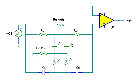
The filter topology here is the Twin T Notch topology. I personally find Twin T topology to be too cricital to be useful in a large scale manufacturing environment. To counteract that, I modify the traditional Twin T discussion to use all equal resistors and all equal capacitors. In this way, you can take advantage of the fact that components manufactured at the same time, by the same manufacturer, using the same process will probably be pretty close in value, and will probably exhibit similar temperature characteristics. There will be a sharp null - somewhere - although component tolerance may put it off a bit. The only real advantage to Twin T notch filters is that they are a single op amp topology, which may be an important factor in applications that are critical on board space and power. If at all possible - use the Fleige topology instead!
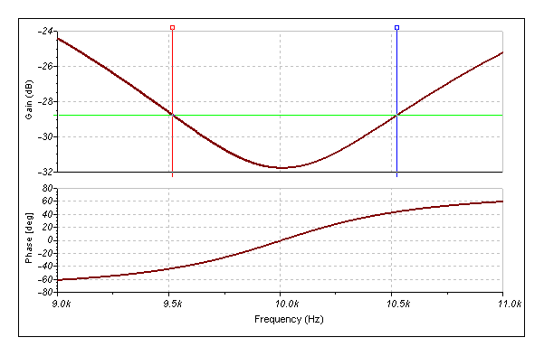
I've also added two resistors that allow some control over the Q, but they also affect notch depth. The Q of a Filter is traditionally measured by taking the bandwidth between the points where the response is down 3 dB. But in the case of notch filters, that number is not very useful at all. I prefer to think of a "reverse Q", where the response rises by 3dB from the deepest point of the notch. This gives a better idea of the bandwidth in the vicinity of the notch and also makes the math very close to the Q calculations for a narrow bandpass filter. The following figure illustrates this concept of "reverse Q":

Away from the notch, Twin-T notch filter Q is pretty poor to begin with compared with the Fleige - another reason to think of using the Fleige instead. It won't disturb other frequencies nearly as much. Back to the Twin T - the trim resistors just make the notch a little wider - which may allow it to hit its target frequency more easily. The Q resistors are varied in a 2 to 1 ratio - take Ro and multiply it by 10 to get Rq1, divide it by 20 t get Rq2 for example. There isn't much range of adjustment before notch depth erodes to the point it isn't worth using the filter, so don't overdo it. To get the deepest notch - make Rq1 open and Rq2 zero.
The Twin T band pass filter gain is unity away from the notch. It is possible to cascade two or more networks inside the feedback loop. For more on this subject, look at the wide notch.
The Twin T Notch topology is sensitive to the input impedance of the op amp. Use a JFET or other high input impedance op amp to make it work properly.
