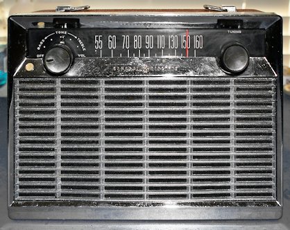
This restoration project is for a piece of radio history. There had been several transistor radios produced in the 1950's, but they were very limited in reception capability. It was impossible to buy a portable radio that offered the same degree of performance as a home radio. Reception was limited, and sound quality was poor from the tiny boxes. GE, realizing that there might be a market for a high quality portable radio that offered the same performance as a home tabletop radio.
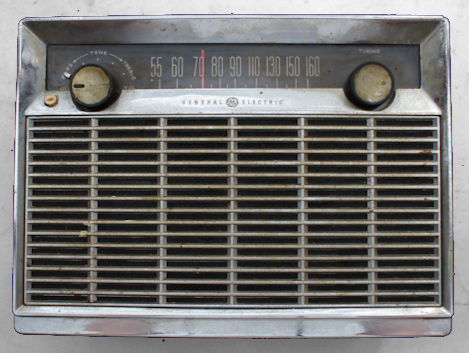
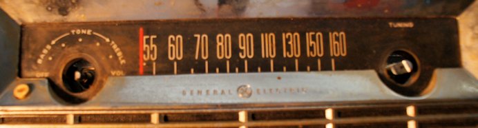
It is not a pocket transistor radio. It is a portable, but is heavy - 11 pounds. It has a five inch speaker, much better than the standard 2 1/4 inch speaker in transistor radios. It is a good DX model, with a true tuned RF stage and three IF filters. It is soundly built, intended to be able to take abuse without damage. Sensitivity and selectivity are very good - almost matching some of their later "Superadio" models. This radio lacks two things that became standard in later models - an internal AC adapater which would allow the radio to be used at home, and a headphone jack.
This is also a real creation of the time in which it was produced. It was the muscle car era - cars had lots of chrome, front grills, organic colors. This - is a muscle radio. Chrome edges, shiny grill - it looks like a radio a muscle car owner could relate to! Throw it in the back seat, take it to the track, listen to the game. Or throw it in the back of a woody with a surfboard, cruise to the beach for some surfing and have your music on the beach, even if you were miles from town. Some people might call it garish - others beautiful.
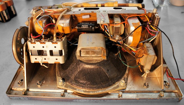
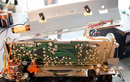
Internally, this radio uses full size components such as its tuning capacitor and IF coils, all of which look like they would be more at home in a tube radio of the time than a portable.
My example of this radio has been around a long time, and suffers a lot from age. So this article is concerned with restoration of the radio - which has a lot of dirt and signs of age. It works, but only gets a couple of strong local stations - so I have a lot of restoration to do. Because it is a piece of radio history, I will try to keep as much as possible original - I will not put in enhancements like ceramic filters and larger ferrite bar. Nor will I add an AC adapter or headphone jack. I won't attept to make it look brand new - it is a bit roached out, and I will leave just enough wear and tear to preserve its history.
This is the procedure I followed, it may or may not be the best procedure, but hopefully you can use it as a guide to do your own restoration work.
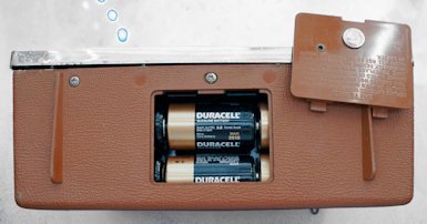
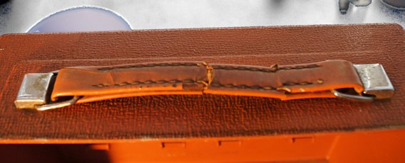
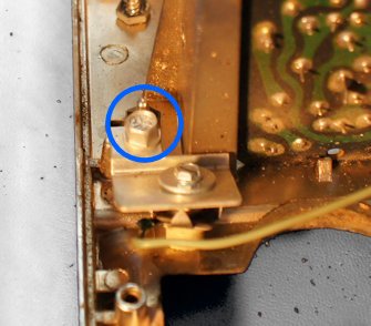
An advanced feature of this radio is a strap that holds connects the battery cover to the radio. This can double as a battery pull. Mine came with the strap disconnected - it is obviously supposed to be attached to the radio with the screws attaching the battery compartment to the cabinet back.
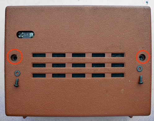
One of the screws on my radio was stripped out - which may be a common failure mode. I am not sure if I want to do the metal work to fill the hole and re-tap.

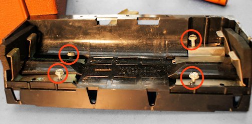
It is a very nice feature of this radio that batteries can all be inserted in the same direction - that is the purpose of the connecting wire. There was some sort of pad material behind the clips.
I elected not to re-install the pads. They had deteriorated to being rock hard.
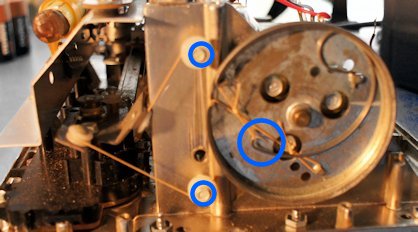
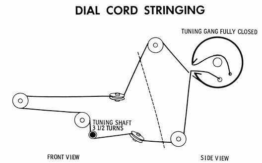
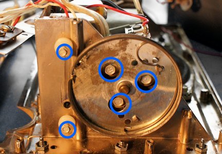
For when you re-assemble the radio, here is the dial string diagram from the service manual:
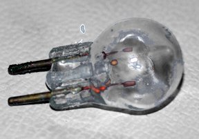
In my one and only nod to modern technology, I was prepared to change these lights to LED, because these bulbs are probably unobtainable. Fortunately for me, both of the bulbs still illuminate.
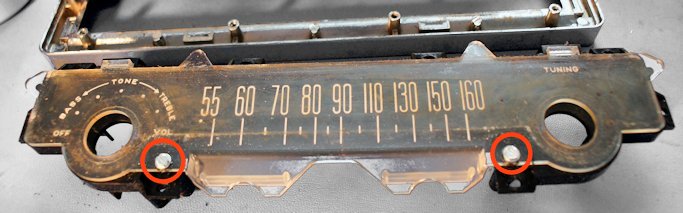
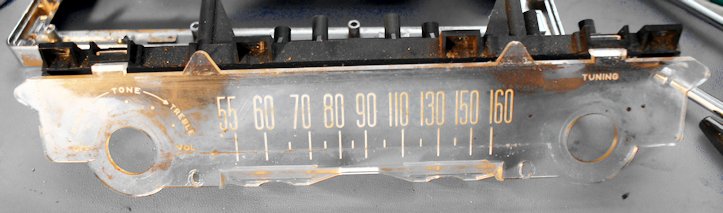
Be extremely careful NOT to try to clean the back of the display with anything but a really soft cloth, lightly applied, to wipe off dust. The silkcreened lettering will come off with any chemical treatment.
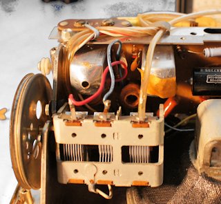
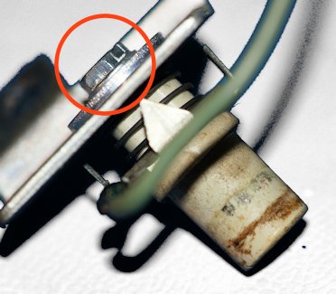
It was necessary for me to disassemble the switch to clean the pushbutton. I took this close-up to show the screw that holds it together, and details of the construction. The fiber washer is under the contact teeth plate, to insulate the spring from the bracket.
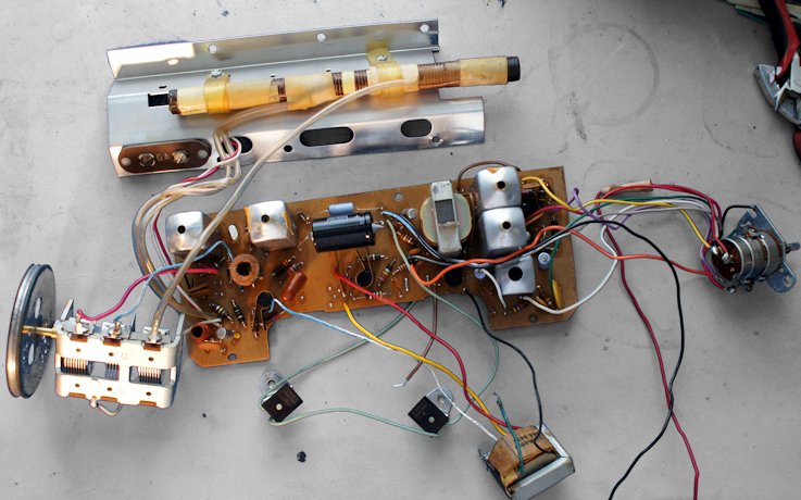
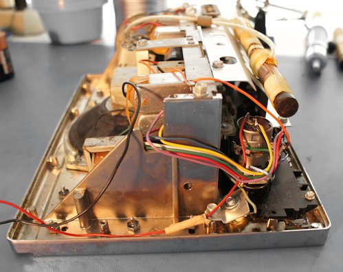
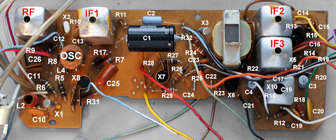
Here is a top view of the PC board. This radio is a later version of the radio - advertised by the seller as a revision "F" - which seems to have more in common with the "H" than the "A".
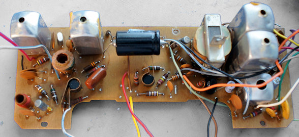
As another restprer noted, it looks like a museum of Germanium transistor types. I suspect more than one are breaking down and not fully functional, but in the interest of maintaining originality, I decided not to do the conversion to silicon - which would require re-baising and added components. If the radio quits working, I will have no choice.
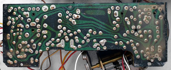
Somebody has already re-capped this radio, and I suspect it was long enough ago that the replacements are also going bad. Their soldering skill slightly damaged a pad, so I will need to be careful. This PC board is also an unusual type - single-sided but with plated through holes. I've seen this a couple of times before - these boards have all the disadvantages of single-sided AND double-sided. It makes soldering a bit more difficult.
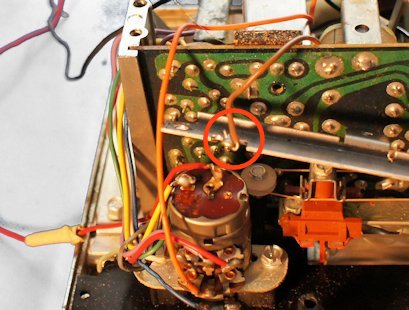
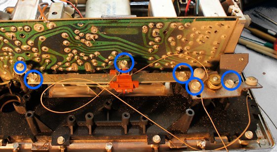
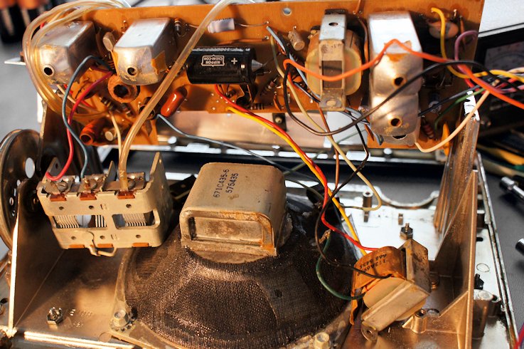
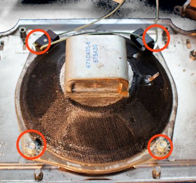
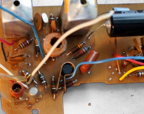
Here is a view of the back side of the PC board.
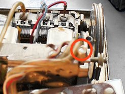
The solder in this radio was a strange formulation of tin / lead and acts like more lead than normal, making PC board work difficult. Nevertheless, I was able to remove the first IF can, take it apart, and fix the intermittent.
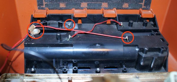
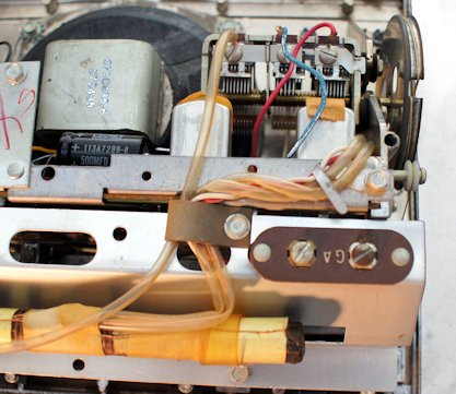
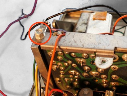
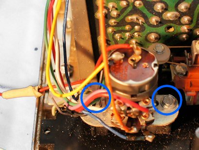
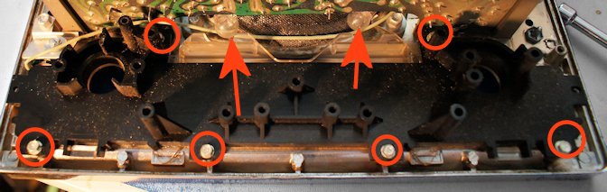
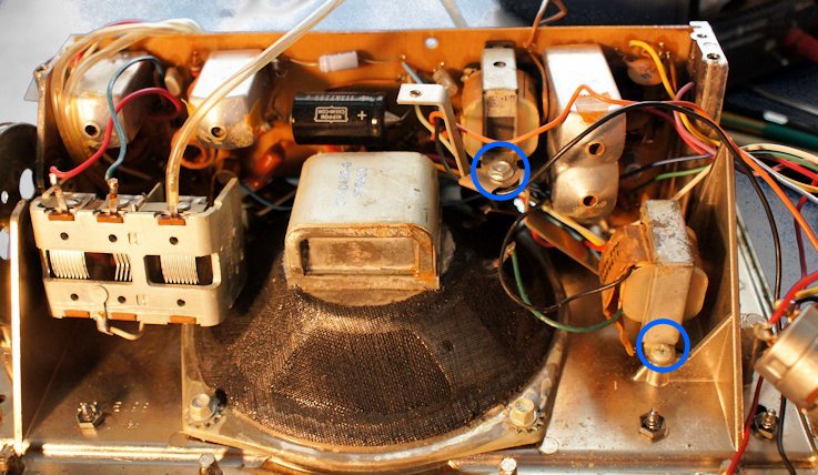
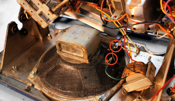
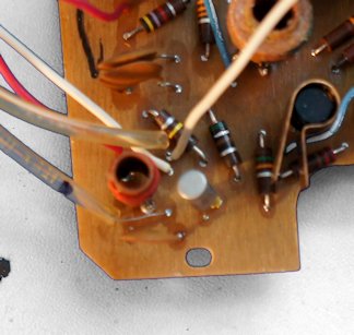
If you want to unsolder some of the wires to make servicing the PC board easier, here are some close-ups of wire routing. A slightly larger hole holds an antenna connection and a white wire. I put a dot on one antenna wire sleeve to identify it.
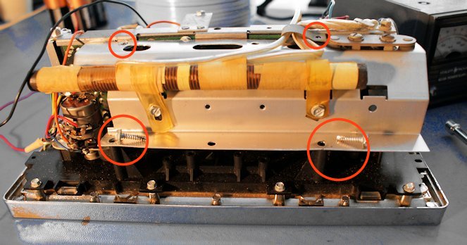
This completes the disasembly of the radio. This is my finished restoration - minus the leather work.
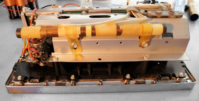
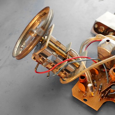
I'm not a fan of the graphic in either manual available on line, so I made my own "silkscreen" version. I think you can figure out the adjustment points on the tuning capacitor (hint - the smaller plates in the middle are oscillator!). I couldn't find an adjustment for the ferrite bar antenna - next time I am in there I may get brave and attack a suspicious looking piece of tape. This may not be a perfect indicator of component locations - my "F" revision varies slightly in board layout from both the "A" and the "H" manuals that are available online. But this is a best guess.
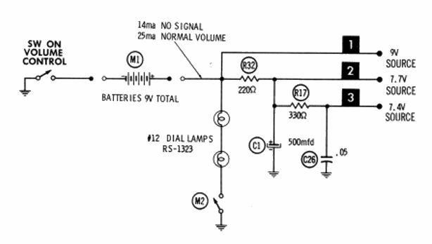
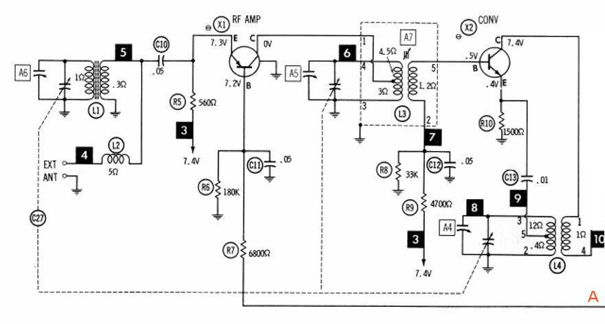
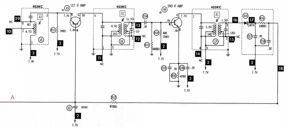
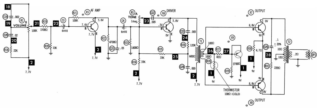
I've cleaned up the "H" schematic as much as I can from the manual, and split it into functional blocks. Again the "F" that I have appears to be slightly different, but the "H" version is closer than the "A". When I get time, I may do an "F" schematic of my radio, but reverse engineering a schematic is NOT an easy job! Sorry if these are a bit big.
Here are some links from other restorers and collectors. I am not responsible for the content or if they are broken.
Radio Jay Allen's page - different versions
Yahoo group - almost inactive though