This is a bit of a personal voyage for me - one of those radios I owned as a boy. The radios I owned taught me a lot about what I know about DX'ing today. But as a boy without perspective on the future, I tended to modify, destroy, discard, and sell the radios on which I learned.
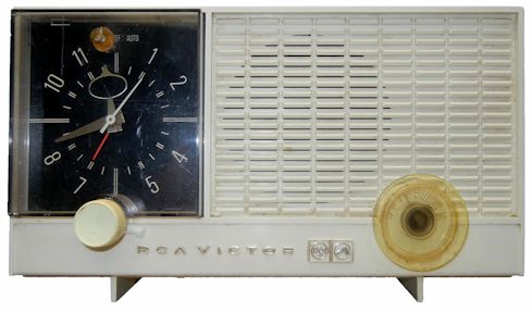
This radio is a rather ordinary "All American Five" tube radio. It was manufactured in the mid 1960's, and was probably one of the last AA5 radios manufactured. It has no metal chassis, all components are PC board mounted - and it was designed to be a clock radio. Whether by design or by accident, the tuning knob has that comfortable orange glow in the center, telling you that the radio is on - as such it has no pilot light.
AM performance is lackluster - distant stations come in about as well as on an average low cost radio. However, this radio is probably one of the last to feature an internal loop antenna instead of a ferrite bar, a fact that had enormous importance to my future as an AM DX'er.
Tube radios are intended to be opened, so the user can change out the tubes. As a safety feature, they are designed to mechanically disconnect the AC line voltage when you remove the back cover, so you aren't exposed to AC voltage when accessing the interior. So a mandatory safety message: Do NOT defeat the purpose of these interlocks. If you do, be prepared for a nasty, potentially fatal shock. I assume no responsibility if you injure or kill yourself. I have warned you - the voltages inside a tube radio are hazardous. Don't do this - EVER! Yes, I violate this rule on this page. I know what I am doing. That doesn't mean you do.


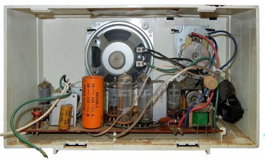
This reveals an issue with the radio. At some point, someone bypassed the 50 uF section of the two section electrolytic capacitor. These capacitors are very likely to fail in radios of this type, so it is not unexpected. Given the hum level of the radio when I turned it on, the capacitor they used to bypass is also defective.

Problem number 2. This radio has been in a dusty environment for a good portion of its life:

YUK! This calls for a complete disassembly. My original plan was to remove all water sensitive components and wash the cabinet by submerging and washing like a dirty dish. I had to modify that plan later.
Unsolder wires from the clock lugs.

Unsolder wires from the speaker.

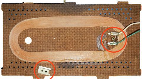
OK, issue number 3 with this radio - the rivet that holds the lug terminal block to the speaker has broken. The radio did have an issue with intermittent audio. This is the cause:

My decidedly low tech solution when I re-assembled was to use glue. The PC board of the radio is now free to slide out from the cabinet. There appears to be provision on the board and cabinet for a screw by the volume control, but I can't see any evidence that there ever was a screw used on this radio.
To remove the clock assembly - it is necessary to remove the power knob from the front of the radio.


There won't be any cleaning / repairing of this clock module - it is held together with rivits.

At this point, I had to make a decision NOT to try to remove the clock face and interior heat reflector to wash the cabinet. I was concerned that I would damage the paper clock face if I submerged it. I took a moist cloth to the cabinet interior instead. I have made a good photograph of the clock face if you want to risk submerging your cabinet.

This photograph shows the tube heat reflector - it is a lot less risky to submerge the cabinet with this left inside.

At this point the radio is pretty much disassembled.
The top of the PC board (with tubes removed) shows the extent of 50 years accumulation of dust and dirt and debris. There was a disgusting dead roach near the disgusting dust bunny that fell off when I removed the board. Obviously a thorough cleaning is in order.

The back side of the PC board:

The connections to the external electrolytic capacitor are made with low temperature speaker wire:

That bad cap was the FIRST to go - and an examination of the underside shows that it had dried out and cracked:

I am NOT a purist when it comes to restoration. When it comes to AC powered radios - most passives need to be replaced, because of years of accumulated heat exposure. Mouser and Digikey have very good selection of components, and it is easy to replace the old components with new ones that are a fraction of the size and perform much better. If I sell the radio in the future, I will include a bag with the original components. Some purists like to hollow out the electrolytic capacitor and place the new caps inside. I don't do that.
The paper / foil capacitors with wax coatings are the next to go. I had some nice molded plastic PC board replacements. I had to drill one hole for the lead on one of them. I also ordered the other capacitors and resistors from Mouser to complete the replacement. Issue number 4 with the radio - at some time in the past, someone had replaced one of the IF transformers with one of those universal replacements. It works OK, but one of the adjustments is made from underneath the board. Originally, two little paper labels covered the holes. I removed them while cleaning the board. Yes - I saved them for purists in the future.
I found a schematic on the web that is fairly close to this radio - several components in the audio amp, however, have been absorbed into one of those old multi-component modules.

A good tube diagram is important to getting the tubes back into the right locations. I usually do a close-up of all such labels on a radio in case I have to reproduce it later.

The final board cleaning was not aggresive - only using 91% alcohol. That other 9% is water, and that takes a while to dry. Be careful of alcohol in stores, you can end up with 70% or even 50% (YUK).

That's all for now - I have considered putting an edge wound loop antenna inside the case of the radio, but I may decide to reproduce my boyhood solution, which took a much larger loop from an old radio that was junked, and put it in between two pieces of cardboard on a stand.