|
MODEL 7-2880A FM/AM PORTABLE RADIO FILE TAB 7 | ||||||
Re-typed in HTML format, remaining as faithful as possible to the original.
|
MODEL 7-2880A FM/AM PORTABLE RADIO FILE TAB 7 | ||||||
CAUTION: THIS MANUAL IS DESIGNED FOR USE BY QUALIFIED ELECTRONIC TECHNICIANS ONLY. CONSUMER
USERS ARE URGED TO CONTACT QUALIFIED FACTORY AUTHORIZED SERVICE FACILITIES FOR REPAIRS.
|  |
| SERVICE SPECIFICATIONS | |||||||||||||||||||||||||||||||||||||
|
|
||||||||||||||||||||||||||||||||||||
| AM Generator - RF Radiated Signal Modulated 30% at 400 Hz | |||||
| GENERATOR FREQUENCY |
RADIO DIAL SETTING |
INDICATOR | ADJUST | REMARKS | |
| 1. | 455 kHz | Closed | Output Meter Across Speaker |
T4, T5, T6, T9 | Adjust for maximum. Repeat until no further improvement is noted. |
| 2. | 1630 kHz | Open | C1L | Adjust for maximum | |
| 3. | 510 kHz | Closed | L5 | Adjust for maximum. Repeat steps 2 and 3 until set will tune to both band end frequencies. |
|
| 4. | 1400 kHz | Tune to Signal | C1J, C1K | Adjust for maximum | |
| 5. | 580 kHz | Tune to Signal | T10, L6 | Adjust for maximum. Repeat steps 4 and 5 until no further improvement is noted. |
|
| High Side of FM Sweep Generator thry a 0.04uF capacitor to TP1, Use only enough Marker Signal for Indication. | |||||
| GENERATOR FREQUENCY |
RADIO DIAL SETTING |
INDICATOR | ADJUST | REMARKS | |
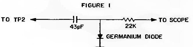
| 1. | 10.7 MHz | Open | Scope at TP2. Use Pad (See Figure 1) |
T1, T2, T3 | Adjust for maximum gain and symmetry. Repeat as necessary. |
| 2. | 10.7 MHz | Open | Scope at TP3. Use Pad (See Figure 2) |
T7, T8 | Adjust for maximum gain and symmetrical S-Curve |
| FM Generator - Modulated RF Radiated Signal | |||||
| 3. | 109.0 MHz | Open | Output Meter Across Speaker |
C15 | Adjust for maximum. |
| 4. | 87.5 MHz | Closed | L4 | Spread or compress coil wind- ings slightly to raise or lower frequency. Repeat Steps 3 and 4 |
|
| 5. | 108.0 MHz | Tune to Signal | C1G, C1H | Adjust for maximum. | |
| 6. | 88 MHz | Tune to Signal | L1, L2 | Spread or compress coil wind- ings slightly to obtain optimum alignment. Repeat Steps 5 and 6 |
|
| 1. | Tune FM dial to a no signal area near the center of the FM Band (98 MHz). |
| 2. | With the AFC switch S2 in OFF position, connect a high impedance voltmeter (Triplett 630-NS or equivalent) to S2 pin A1 and measure the D.C. voltage. Note: Voltemeter chosen must not cause noise in FM Band which would cause incorrect alignment. |
| 3. | Next connect voltmeter to S2 pin A2 and adjust R17 trim pot to the same voltage as measured in Step 2. Accuracy of voltage adjustment to voltage measured in Step 2 should be better than +/- 5%. |
CABINET DISASSEMBLY
TO SERVICE CIRCUIT BOARDS To simplify servicing, troubleshoot from component side of circuit board whenever possible, using the component layout top view. To prevent damage to cabinet front and speaker, it is suggested that speaker leads be disconnected at speaker |
TO SERVICE CIRCUIT BOARDS, Cont'd terminals and an 8 Ohm external test speaker be connected to earphone jack while servicing radio.
|
 |
 |
Click image to see full size version: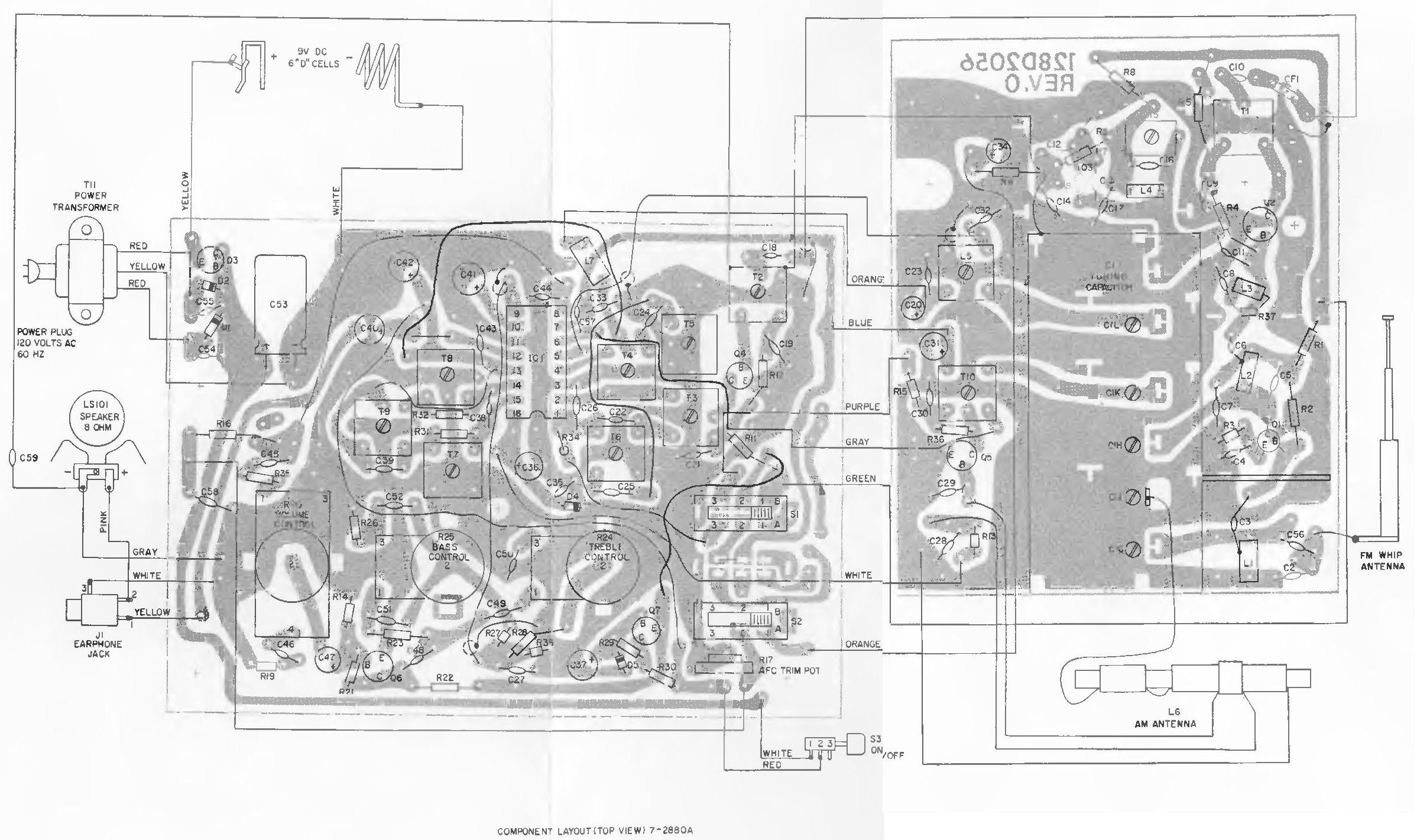
Click image to see full size version:
Click image to see full size version:
REPLACEMENT PARTS LIST - MODEL 7-2880A
|
| |||||||||||||||||||||||||||||||||||||||||||||||||||||||||||||||||||||||||||||||||||||||||||||||||||||||||||||||||||||||||||||||||||||||||||||||||||||||||||||||||||||||||||||||||||||||||||||||||||||||||||||||||||||||||||||||||||||||||||||||||||||||||||||||||||||||||||||||||||||||||||||||||||||||||||||||||||||||||||||||||||||||||||||||||||||||||||||||||||||||||||||||||||||||||||||||||||||||||||||||||||||||||||||||||||||||||
Replacement parts may be ordered from; General Electric Co., Parts and Accessory Yervice, 1900 Bleecker St., Utica, N.Y. 13501
Note: CA and MS references are for factory use only
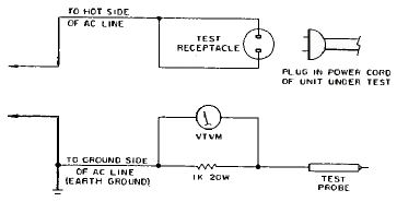
IMPORTANT
PERFORM THE FOLLOWING SAFETY CHECKS AFTER SERVICING THIS UNIT:
If meter reading indicates less than 3 volts on all test points, set meter to low (3V AC) scale and repeat test. |
|
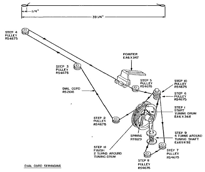
DIAL CORD STRINGING INSTRUCTIONS
|
To restring dial cord, it will be necessary to remove chassis
|
THIS SUPPLEMENT CONTAINS UPDATED OR ADDITIONAL REPLACEMENT PARTS and SERVICE INFORMATION.
PARTS LIST REVISIONS TO DATE
| CORRECT CAT. NO. |
REF. NO. | DESCRIPTION | REVISION |
| EA82X50 | MS-2 | Whip Antenna | Was EA2X50 |
| EA49X520 | R17 | Trim Pot | Was RT2410 |
| EA36X509 | L2 | FM RF Coil | Was RT4722 |
| EA39X254 | SW3 | Power ON/OFF Switch |
Was EA39X196 |
| EA36X71 | L8 | RF Choke | Add to Parts List |
CORRECTIONS TO SCHEMATIC
C48 is shown as 47MF On the schematic diagram- Please change to 0.1MF as shown in the Parts List
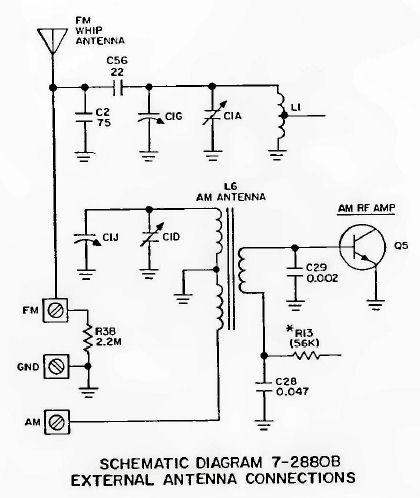
This service manual contains the unique replacement parts list and partial schematic for the model 7-2880B AM/FM Portable Radio. The remaining parts, as well as the schematic, wiring diagram, alignment instructions, are the same as those used in the Model 7-288OA. When servicing this model, also refer to service manual 7-2880A, Pub. #37-6000-79.
UNIQUE REPLACEMENT PARTS LIST
| CAT. NO. | SYMBOL | DESCRIPTION |
| EA98X728 | CA-1 | Cabinet Back w/External Antenna Terminals |
| EA3X264 | MS-1 | External Antenna Terminal |
| EA83X135 | L6 | AM Antenna |
| EA13X218 | R38 | 2.2 Megohm Resistor/Special High Voltage Type |
NOTE: CA and MS References are for factory use only
Replacement parts may be ordered from: General Electric Company, 1900 Bleecker St., Utica, N.Y. I3501