|
MODEL 7-2885A/B/C FM/AM PORTABLE RADIO FILE TAB 7 | ||||||
Re-typed in HTML format, remaining as faithful as possible to the original.
|
MODEL 7-2885A/B/C FM/AM PORTABLE RADIO FILE TAB 7 | ||||||
CAUTION: THIS MANUAL IS DESIGNED FOR USE BY QUALIFIED ELECTRONIC TECHNICIANS ONLY. CONSUMER
USERS ARE URGED TO CONTACT QUALIFIED FACTORY AUTHORIZED SERVICE FACILITIES FOR REPAIRS.
|  |
| SERVICE SPECIFICATIONS | |||||||||||||||||||||||||||||||||||||
|
|
||||||||||||||||||||||||||||||||||||
| AM Generator - RF Radiated Signal Modulated 30% at 400 Hz | |||||
| GENERATOR FREQUENCY |
RADIO DIAL SETTING |
INDICATOR | ADJUST | REMARKS | |
| 1. | 455 kHz | Closed | Output Meter Across Speaker |
T4, T5, T6, T9 | Adjust for maximum. Repeat until no further improvement is noted. |
| 2. | 1630 kHz | Open | C1L | Adjust for maximum | |
| 3. | 510 kHz | Closed | L5 | Adjust for maximum. Repeat steps 2 and 3 until set will tune to both band end frequencies. |
|
| 4. | 1400 kHz | Tune to Signal | C1J, C1K | Adjust for maximum | |
| 5. | 580 kHz | Tune to Signal | T10, L6 | Adjust for maximum. Repeat steps 4 and 5 until no further improvement is noted. |
|
| High Side of FM Sweep Generator thry a 0.04uF capacitor to TP1, Use only enough Marker Signal for Indication. | |||||
| GENERATOR FREQUENCY |
RADIO DIAL SETTING |
INDICATOR | ADJUST | REMARKS | |
| 1. | 10.7 MHz | Open | Scope at TP2. Use Pad (See Figure 1) |
T1, T2, T3 | Adjust for maximum gain and symmetry. Repeat as necessary. |
| 2. | 10.7 MHz | Open | Scope at TP3. Use Pad (See Figure 2) |
T7, T8 | Adjust for maximum gain and symmetrical S-Curve |
| FM Generator - Modulated RF Radiated Signal | |||||
| 3. | 109.0 MHz | Open | Output Meter Across Speaker |
C15 | Adjust for maximum. |
| 4. | 87.5 MHz | Closed | L4 | Spread or compress coil wind- ings slightly to raise or lower frequency. Repeat Steps 3 and 4 |
|
| 5. | 108.0 MHz | Tune to Signal | C1G, C1H | Adjust for maximum. | |
| 6. | 88 MHz | Tune to Signal | L1, L2 | Spread or compress coil wind- ings slightly to obtain optimum alignment. Repeat Steps 5 and 6 |
|
| 1. | Tune FM dial to a no signal area near the center of the FM Band (98 MHz). |
| 2. | With the AFC switch S2 in OFF position, connect a high impedance voltmeter (Triplett 630-NS or equivalent) to S2 pin A1 and measure the D.C. voltage. Note: Voltemeter chosen must not cause noise in FM Band which would cause incorrect alignment. |
| 3. | Next connect voltmeter to S2 pin A2 and adjust R17 trim pot to the same voltage as measured in Step 2. Accuracy of voltage adjustment to voltage measured in Step 2 should be better than +/- 5%. |
 |
 |
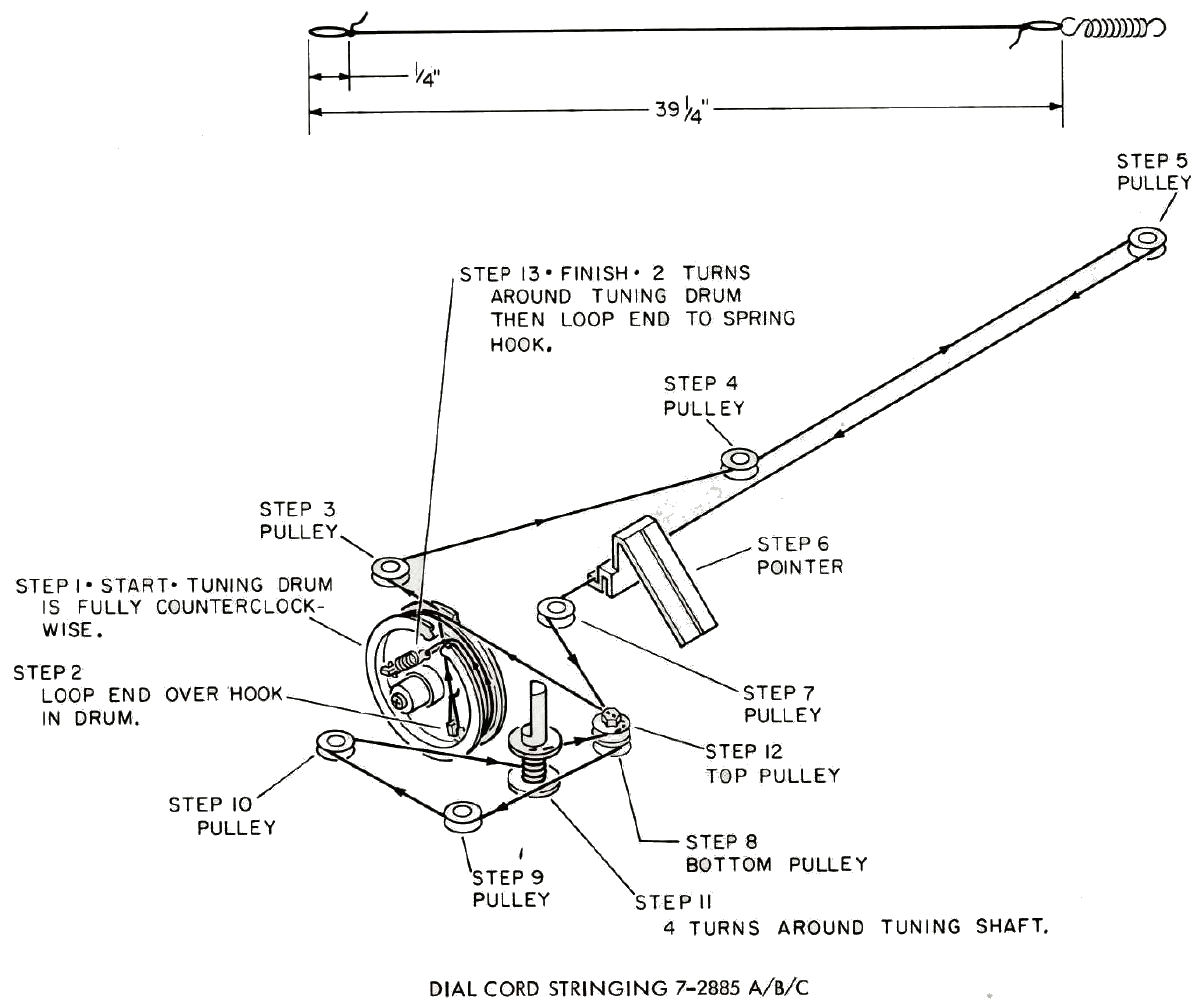
Click image to see full size version:
Click image to see full size version: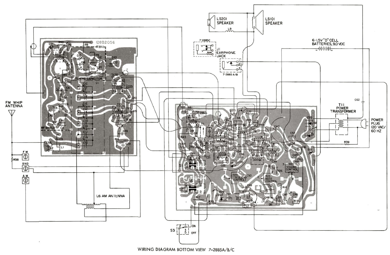
Click image to see full size version:
REPLACEMENT PARTS LIST - MODEL 7-2880A
|
| |||||||||||||||||||||||||||||||||||||||||||||||||||||||||||||||||||||||||||||||||||||||||||||||||||||||||||||||||||||||||||||||||||||||||||||||||||||||||||||||||||||||||||||||||||||||||||||||||||||||||||||||||||
| Replacement parts may be ordered from: General Electric Company, National Parts Distribution, P. O. Box 7025, Charlotte, N.C. 28217 or in CANADA - Canadian General Electric, 80 Bradford Street, P. O. Box 1060, Barrie, Ontario L4M5E1. |
Click image to see full size version: