| Technical Publications P O Box 1976/ Indianapolis Indiana 46206 |
Technical Publications 6540 Tomken Road/ Mississuaga, Ont L5T 2E9 |
SERVICE DATA INDEX
| PAGE NUMBER |
||
| Alignment | . . . . . . . . . . . . . . . . . . . . . . . . . . . . . . . . . . . . . . . . . . . . . . . . . . . . | 3 |
| Replacement Parts | . . . . . . . . . . . . . . . . . . . . . . . . . . . . . . . . . . . . . . . . . . . . . . . . . . . . | 4 |
| Safety Check | . . . . . . . . . . . . . . . . . . . . . . . . . . . . . . . . . . . . . . . . . . . . . . . . . . . . | 2 |
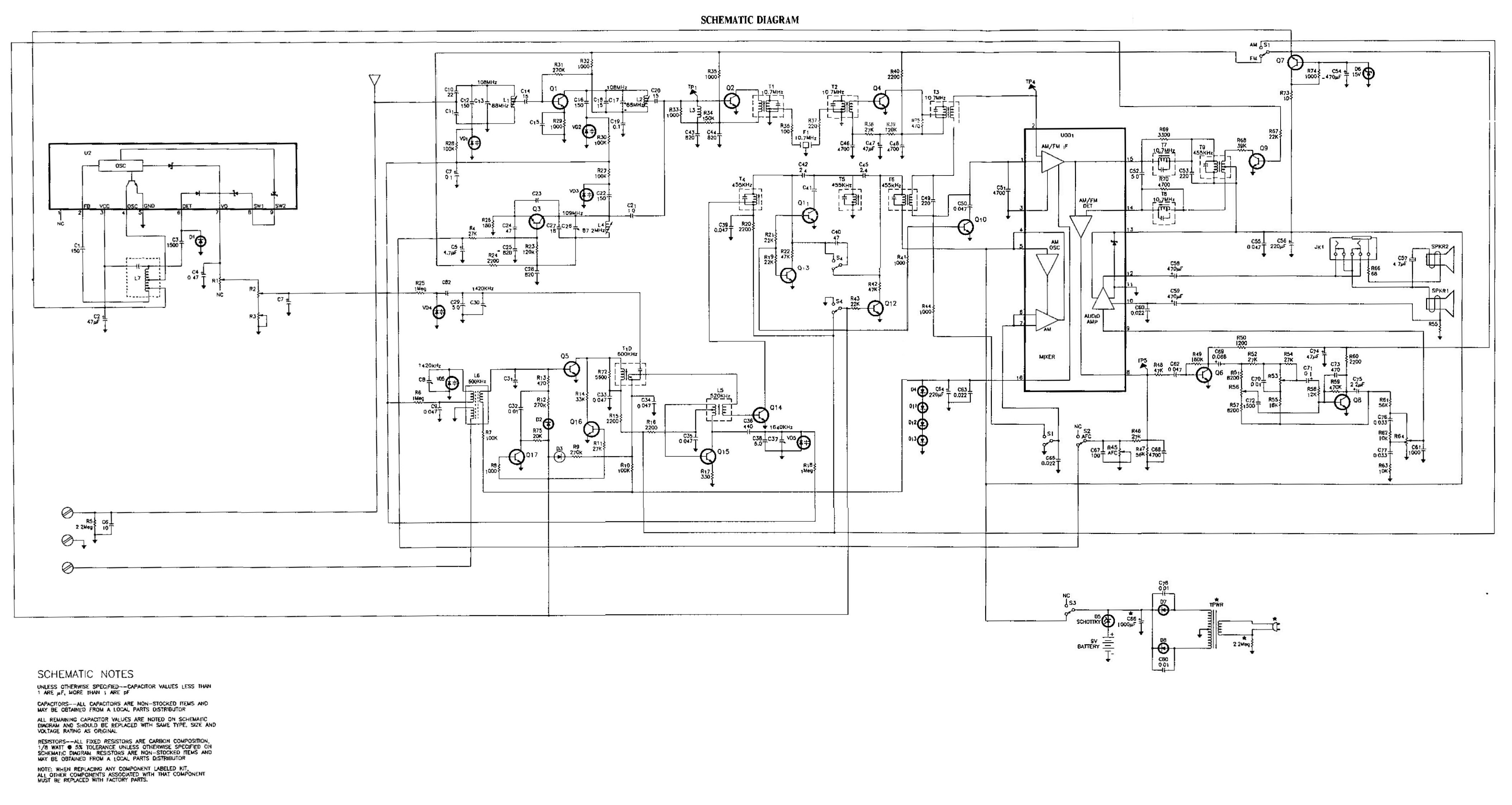
| Schematic Dragram | . . . . . . . . . . . . . . . . . . . . . . . . . . . . . . . . . . . . . . . . . . . . . . . . . . . . | 5 |
SAFETY NOTICE
|
Components having special safety characteristics are identified by stars (*) on schematics and on the parts list in this Service Data and its bulletins. Before servicing this instrument, it is important that the service technician read and follow all applicable "Safety Precautions" and "Product Safety Notices". |
| First Edition .. First Printing Copyright 1992 .. Thomson Consumer Electronics, Inc. Printed in USA .. Trademark(s) Registered .. Marca(s) Registrada(s) |
SM72887A |
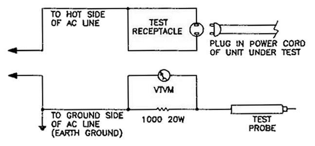
SAFTY CHECK
Perform the following safety cheek after servicing this unit.
|
|
ALIGNMENT PROCEDURE
ALIGNMENT PROCEDURE
AM ALIGNMENT - FUNCTION SWITCH IN AM POSITION
| AM Generator - RF Radiated Signal Modulated 30% at 400 Hz | |||||
| GENERATOR FREQUENCY |
RADIO DIAL SETTING |
INDICATOR | ADJUST | REMARKS | |
| 1. | 455 kHz | Low End | Output Meter Across Speaker |
T4, T5, T6, T9 | Adjust for maximum. |
| 2. | 1640 kHz | High End | C37 | Adjust for maximum | |
| 3. | 520 kHz | Low End | L5 | Adjust for maximum. Repeat steps 2 and 3 for band ends. |
|
| 4. | 1420 kHz | Tune to Signal | C8, C30 | Adjust for maximum | |
| 5. | 600 kHz | Tune to Signal | T10, L6 | Adjust to obtain maximum output. Repeat steps 4 and 5 until no further improvement is noted. |
|
FM ALIGNMENT - FUNCTION SWITCH IN FM POSITION
| High Side of FM Sweep Generator thru a 5pF capacitor in series with 68 Ohm resistor to TP1. Use only enough Marker Signal for Indication. |
|||||
| GENERATOR FREQUENCY |
RADIO DIAL SETTING |
INDICATOR | ADJUST | REMARKS | |
| 1. | 10.7 MHz | Low End | Scope at TP4 | T1, T2, T3 | Adjust for maximum gain and symmetry. Repeat as necessary. |
| 2. | 10.7 MHz | Low End | Scope at TP5 | T7, T8 | Adjust for symmetrical S-Curve using strong signal. |
| FM Generator - Modulated RF Radiated Signal | |||||
| 3. | 109.0 MHz | High End | Output Meter Across Speaker |
C26 | Adjust for maximum. |
| 4. | 87.2 MHz | Low End | L4 | Spread or compress coil windings slightly to raise or lower frequency. Repeat Steps 3 and 4 |
|
| 5. | 108.0 MHz | Tune to Signal | C13, C17 | Adjust for maximum. | |
| 6. | 88.1 MHz | Tune to Signal | L1, L2 | Spread or compress coil windings slightly to obtain optimum alignment. Repeat Steps 5 and 6 |
|
NOTE: Scope used must have at least 50 mV/CM sensitivity and sweep generator at least 200mV output.
L7 ALIGNMENT
|
|
R1 ALIGNMENT Set band switch to FM position and AFC switch to off.
|
|
AFC ALIGNMENT Set radio frequency to 98MHz and AFC switch to off.
|
REPLACEMENT PARTS
| Ref. No. | Cat. No. | Description | Ref. No. | Cat. No. | Description |
| CABINET AND CHASSIS | |||||
| CA60 | 98A20159 | CABINET, FRONT | CA76 | 43A20169 | KNOB |
| CA61 | 98A20160 | CABINET, BACK | CA84 | 95A20170 | SPEAKER, 6-1/2" |
| CA63 | 9A20161 | DOOR, BATTERY | CA85 | 95A20171 | SPEAKER, 2" |
| CA65 | 90A20162 | CRYSTAL, DIAL | CA86 | 88A20172 | *TRANSFORMER, POWER |
| CA66 | 90A20163 | CRYSTAL, TOP | CA90 | EA66X87 | *CORD, POWER |
| CA67 | 78A20164 | HANDLE | C102 | 5-1992 | ANTENNA, WHIP |
| CA69 | 89A20165 | GRILLE, SPEAKER | CA104 | 2A20173 | SPRING, BATTERY |
| CA70 | 43A20166 | KNOB, TUNING | CA105 | EA2X1893 | CONTACT, BATTERY |
| CA72 | 43A20167 | KNOB | CA106 | 2A20174 | SPRING, CONICAL |
| CA74 | 43A20168 | KNOB, POWER | |||
| ELECTRICAL | |||||
| C66 | 31A19120 | *CAP LYTC 1000uF 16V | Q9 | EA15X1061 | TRANSISTOR C732TM |
| D1 | EA16X503 | DIODE 1S1588 | Q10 | EA16X1061 | TRANSISTOR C732TM |
| D2 | EA16X878 | DIODE 1N4148 | Q11 | EA15X1061 | TRANSISTOR C732TM |
| D3 | EA16X878 | DIODE 1N4148 | Q12 | EA15X1061 | TRANSISTOR C732TM |
| D4 | EA16X878 | DIODE 1N4148 | Q13 | EA15X1061 | TRANSISTOR C732TM |
| D5 | EA16X941 | DIODE | Q14 | EA15X681 | TRANSISTOR 2SC1923 |
| D6 | EA16X854 | DIODE ZENER | Q15 | EA15X681 | TRANSISTOR 2SC1923 |
| D7 | EA57X14 | DIODE 1N4002 | Q16 | EA15X1061 | TRANSISTOR C732TM |
| D8 | EA57X14 | DIODE 1N4002 | Q17 | EA15X1061 | TRANSISTOR C732TM |
| D9 | EA57X14 | DIODE 1N4002 | R53 | 49A20177 | RES CONTROL |
| D10 | EA57X14 | DIODE 1N4002 | R56 | 49A20177 | RES CONTROL |
| D11 | EA16X878 | DIODE 1N4148 | R64 | EA49X881 | RES CONTROL |
| D12 | EA16X878 | DIODE 1N4148 | S1 | 39A20178 | SWITCH |
| D13 | EA16X878 | DIODE 1N4148 | S2 | 39A20178 | SWITCH |
| F1 | EA41X780 | FILTER CERAMIC FM | S3 | EA39X1115 | SWITCH |
| J1 | EA41X844 | JACK PHONE STEREO | S4 | 39A20178 | SWITCH |
| Q1 | EA15X7242 | TRANSISTOR | U1 | EA33X9431 | IC AM/FM |
| Q2 | 15A20175 | TRANSISTOR | VD1 | 16A20150 | DIODE VARACTOR |
| Q3 | 15A20176 | TRANSISTOR | VD2 | 16A20150 | DIODE VARACTOR |
| Q4 | EA15X1422 | TRANSISTOR C380TM | VD3 | 16A20150 | DIODE VARACTOR |
| Q5 | 15A20176 | TRANSISTOR | VD4 | 16A20150 | DIODE VARACT0R |
| Q6 | EA15X4335 | TRANSISTOR | VD5 | 16A20179 | DIODE VARACTOR |
| Q7 | EA15X4335 | TRANSISTOR | VD6 | 16A20179 | DIODE VARACTOR |
| Q8 | EA15X1061 | TRANSISTOR CT732M | UC7887A | USE and CARE GUIDE | |
|
NOTE: "CA", "MS" and "TM" referenceses are for factory use only. Parts not listed or listed without catalog number are non- stocked items. Capacitors, resrstors and items not listed are non-stocked items. All such items should be replaced with same type, size and rating as original. |
Parts marked on the schematic and in the parts list with a "*" are safety critical and must be replaced wrth factory replacement parts in order to maintain the safety chamctenstics of the Instrument. |
||||
Click image to see full size version: