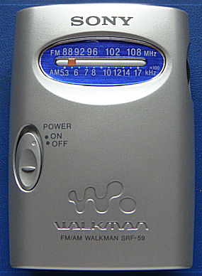
The Sony SRF-59 is a highly touted "ultralight" DX portable. At less than $20, it was worth the gamble - as a portable I can easily throw into a bag when I travel. But - is it really good as a DX model? If so - what is "under the hood" that makes it so good?
First impressions with the radio confirmed - it is no slouch, unmodified and out of the box. Performance is almost as good as the legendary SRF-A1 portable, of which I own two. I seldom use them as "ultralights", however, because they are a bit on the clunky side. A third of the SRF-A1 interior is dedicated to AM stereo, which is used by fewer and fewer stations. But I digress - from a Houston listening locations, stations from Austin, San Antonio, and Dallas are clearly audible on AM. Houston was not a good benchmark for FM, but from a Dallas location all of the rim shots such as KLAK are clearly audible, a very impressive feat for a walkman with nothing but headphone wire antenna. Ultralight DX radio? You bet!
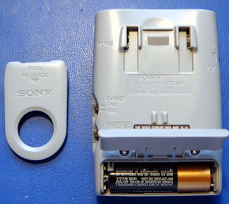
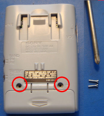
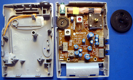
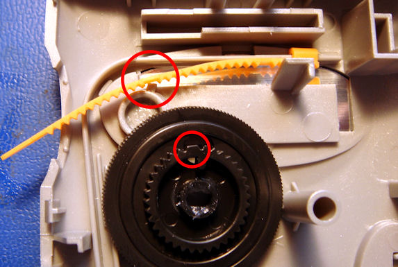
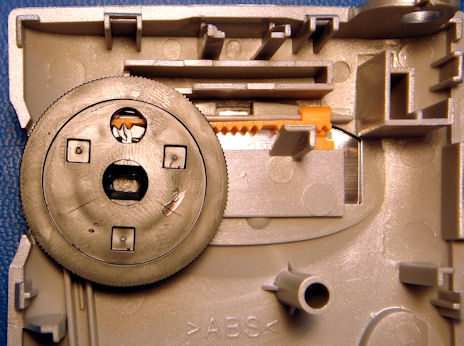
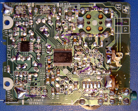
OK, at this point you have discovered a problem. You absolutely WILL disassemble the dial indicator assembly. It is inevitable because the board is glued against the back of the case with a strong adhesive. Don't worry, I will show you how to re-assemble later. It is very easy! Here is a view of the radio interior, with the dial knob at the right:
There are no free service manuals for the SRF-59 on line. There is a manual for a very similar model, the SRF-PSY03, on line. So what I have done is taken the relevant portions of that manual and grafted them together into an approximation of the SRF-59 manual. Some of this information is available on line other places, but I've done high resolution scans and worked extensively with the images to make them crisp and clear. When you see a reduced version with a blue link box around it, simply click on it and the full sized image will come up in the browser. I've also taken some information on the IC and created a new "theory of operation" section to the manual, because this is no ordinary superhet - there is some real sophistication here!
Without further ado - here is what I've got so far:
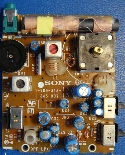
I think my photos above are better, but somebody went to a lot of trouble:
This section contains a summary of information presented in a paper published about the IC. The original paper is linked at the bottom of the page - but be warned it is written by writers whose native language is not English, and they tend to repeat themselves. What they have done in the IC is really amazing - it addresses some of the obvious problems in superheterodyne receiver design and corrects them.
Consult the block diagram while reading through this description. A more detailed block diagram of the IC is included in the Schematic section as well.
The CXA1129 integrated circuit forms the heart of the radio. The FM band is dual conversion, the first FM IF frequency is 30 MHz and the second is 150 kHz. The AM IF frequency is 55 kHz. These selections provide excellent selectivity far beyond what would be possible with conventional IF frequencies of 10.7 MHz and 455 kHz. The final FM IF amplifier is actually a low pass filter, high pass filtering being unnecessary in this dual conversion scheme. The reason why the IC designers lowed the IF frequencies is that there is a fundamental limit in high speed filter design - the open loop bandwidth limit of op amps. While a 455 kHz IF amplifier might be realizable, a 10.7 MHz IF filter with any appreciable gain would require a unity gain open loop response in the GHz region. There are fundamental limits in semiconductor processes - an IC process designed for that type of speed might not be usable for the rest of the IC, and would certainly boost power supply current. It also might not be compatible with the extremely low power supply voltage. The selection of a low pass filter topology in the last FM IF stage, as I mentioned, is because a bandpass is unnecessary in the final IF stage. But it also lowers the requirement for open loop gain in the op amps, because low pass filters require less overhead than bandpass.
An inherent problem with low IF frequency receivers is that image rejection is also low. The IC designers have countered that problem by using a quadrature mixing scheme. The oscillator frequency from the second local oscillator generated as a zero degree as well as a 90 degree phase shifted oscillator frequency. There are two mixers, MIX1 and MIX2, one for the zero degree local oscillator, and one for the 90 degree phase shifted local oscillator. The mixer products produced are then presented to PSN1 and PSN2 phase shift networks, which produce an additional 90 degrees of relative phase shift. The two phase shifted mixer output are summed together, passing the desired signal and cancelling the image. The desired signal is passed to the final IF filters.
The FM signal path comes from the antenna, which is also the return line for the headphones. To eliminate relatively high power audio, it is band pass filtered to the FM band in BPF1. The external antenna can be disconnected by S1 to reduce sensitivity in "local" mode. FM RF comes into the CXA1129 through the FM RF In pin, where the tuned FM RF amp amplifies it by 10dB. The RF amp is tuned by L1 and section 2 of the tuning capacitor. The FM oscillator tuning circuit consisting of L6 and section 1 of the tuning capacitor is connected to the FM OSC input, which operates 30 MHz above the received station's frequency. This is then connected to the FM mixer, creating a 30 MHz IF.
The AM ferrite bar antenna L5 is tuned with section 4 of the tuning capacitor, and connected to the AM RF amplifier input. L3 and tuning capacitor section 3 tune the AM local oscillator, which is also the FM second local oscillator. L2 is connected to this oscillator to form a second local oscillator frequency for FM. Both of these local oscillator frequencies are divided by two, so that quadrature oscillator output can be formed for each band.
Both the FM and AM signal paths are connected to dual quadrature mixers, which operate to reduce images as described above.
The second FM IF filter is a 9th order low pass filter, with a cutoff frequency of 300 kHz. It gives a selectivity comparable to three ceramic filters. Alternate channel selectivity is over 40 dB.
The AM IF amplifer consists of three second order biquad 55 kHz bandpass filters. Adjacent channel selectivity is 35 dB.
FM discrimination is done by a pulse count circuit. The IC article doesn't give any detail about how AM detection is done, presumably it is done by envelope detection.
Stereo decoding is done in a manner similar to the FM second mixer, because the second harmonic of the IF freqency (300 kHz) beats with 38 kHz. They combat the problem by doing a quadrature generation of the 19 kHz reconstructed carrier. Other than tan, multiplex detection is a pretty standard phase locked loop implementation. The 38 khz oscillator is tuned by L4.
Audio is amplified in a separate audio amp IC, which has a 30 mW output level for headphones.
BAND Switch Setting: AM
BAND Switch Setting: FM
| AM FREQUENCY COVERAGE ADJUSTMENT | |
|---|---|
| Adjust for a maximum reading on level meter | |
| L3 | 520 kHz |
| CT1 (3/4) | 1,750 kHz |
| AM TRACKING ADJUSTMENT | |
|---|---|
| Adjust for a maximum reading on level meter | |
| L5 | 600 kHz |
| CT1 (4/4) | 1,400 kHz |
| FM FREQUENCY COVERAGE ADJUSTMENT | |
|---|---|
| Adjust for a maximum reading on level meter | |
| L6 | 86.5 MHz |
| CT1 (1/4) | 109.5 MHz |
| FM TRACKING ADJUSTMENT | |
|---|---|
| Adjust for a maximum reading on level meter | |
| L1 | 86.5 MHz |
| CT1 (2/4) | 109.5 MHz |
2nd Local Frequency (57.1 MHz) Adjustment
Setting: BAND switch: FM
Connection:
Procedure:
Specification values: 56.5 to 57.0 MHz
FM STEREO (38 kHz) Adjustment
Setting: BAND switch: FM
Connection:
Procedure:
Ref. No.  Part No.        Description            Remark
BPF1      1-236-711-21    FILTER, BAND PASS
C2        1-163-101-00    CERAMIC CHIP           22PF, 5%, 50V
C3        1-126-163-11    ELECT                  4.7uF, 20%, 50V
C4        1-163-181-00    CERAMIC CHIP           100PF, 5%, 50V
C5        1-163-220-11    CERAMIC CHIP           3PF, 0.25PF, 50V
C6        1-163-143-00    CERAMIC CHIP           0.0012uF, 5%, 50V
C7        1-162-638-11    CERAMIC CHIP           1uF, 16V
C8        1-164-004-11    CERAMIC CHIP           0.1uF, 10%, 25V
C10       1-164-222-11    CERAMIC CHIP           0.22uF, 25V
C11       1-163-023-00    CERAMIC CHIP           0.015uF, 5%, 50V
C12       1-163-023-00    CERAMIC CHIP           0.015uF, 5%, 50V
C13       1-162-638-11    CERAMIC CHIP           1uF, 16V
C14       1-162-638-11    CERAMIC CHIP           1uF, 16V
C15       1-163-087-00    CERAMIC CHIP           4PF, 50V
C16       1-162-638-11    CERAMIC CHIP           1uF, 16V
C17       1-163-104-00    CERAMIC CHIP           30PF, 5%, 50V
C18       1-124-257-00    ELECT                  2.2uF, 20%, 50V
C19       1-163-038-00    CERAMIC CHIP           0.1uF, 25V
C20       1-104-665-11    ELECT                  100uF, 20%, 16V
C21       1-126-163-11    ELECT                  4.7uF, 20%, 50V
C22       1-104-942-11    ELECT                  1uF, 20%, 50V
C23       1-104-396-11    ELECT                  10uF, 20%, 16V
C24       1-104-942-11    ELECT                  1uF, 20%, 50V
C25       1-163-117-00    CERAMIC CHIP           100PF, 5%, 50V
C26       1-163-117-00    CERAMIC CHIP           100PF, 5%, 50V
C27       1-126-154-11    ELECT                  47uF, 20%, 6.3V
C28       1-164-004-11    CERAMIC CHIP           0.1uF, 10%, 25V
C29       1-124-463-00    ELECT                  0.1uF, 20%, 50V
C30       1-124-463-00    ELECT                  0.1uF, 20%, 50V
C31       1-124-442-00    ELECT                  330uF, 20%, 6.3V
C32       1-126-154-11    ELECT                  47uF, 20%, 6.3V
C33       1-126-154-11    ELECT                  47uF, 20%, 6.3V
C34       1-163-117-00    CERAMIC CHIP           100PF, 5%, 50V
C35       1-163-141-00    CERAMIC CHIP           0.001uF, 5%, 50V
C37       1-163-141-00    CERAMIC CHIP           0.001uF, 5%, 50V
C38       1-163-085-00    CERAMIC CHIP           2PF, 50V
CV1       1-151-700-11    CAP, VAR (TUNE)
D1        8-719-991-33    DIODE                  1SS133T-77
D2        8-719-991-33    DIODE                  1SS133T-77
HPJ1      1-563-857-11    JACK, HEADPHONE
IC1       8-752-061-76    IC                     CXA1129N-T4
IC2       8-759-822-48    IC                     LA4537M
J1        1-216-296-00    SHORT                  0
J2        1-216-295-00    SHORT                  0
J3        1-216-295-00    SHORT                  0
J4        1-216-295-00    SHORT                  0
J5        1-216-295-00    SHORT                  0
L1        1-428-781-11    COIL, AIR-CORE
L2        1-428-780-11    COIL, AIR-CORE
L3        1-406-477-11    COIL (AM OSC)
L4        1-406-476-21    COIL (VCO)
L5        1-402-609-11    ANTENNA, FERRITE-ROD
L6        1-428-779-11    COIL, AIR-CORE
L7        1-409-382-11    COIL, TRAP
R1        1-216-061-00    METAL CHIP            3.3K, 5%, 1/10W
R2        1-216-034-00    METAL CHIP            240, 5%, 1/10W
R3        1-216-061-00    METAL CHIP            3.3K, 5%, 1/10W
R4        1-216-061-00    METAL CHIP            3.3K, 5%, 1/10W
R5        1-216-049-11    RES, CHIP             1K, 5%, 1/10W
R6        1-216-311-00    METAL CHIP            6.8, 5%, 1/10W
R8        1-216-304-11    METAL CHIP            3.3, 5%, 1/10W
R9        1-216-304-11    METAL CHIP            3.3, 5%, 1/10W
R10       1-216-073-00    METAL CHIP            10K, 5%, 1/10W
RV1       1-241-890-11    RES, VAR, CARBON      20K/20K
S1        1-571-478-11    SWITCH, SLIDE
S2        1-571-478-11    SWITCH, SLIDE
S3        1-571-478-11    SWITCH, SLIDE