The Current State of Radio Design
I have been a radio design expert for almost 45 years. I delved into it as a hobby, and remain an active radio enthusiast and DX'er to this day. I originally got into radio design because the local radio stations in my home town were dismal, and it took DX techniques and some electronics knowledge to hear stations I really wanted to hear.
I am posting this page to show what is currently used in receiver design. I can tell you truthfully that most current radios and radio containing devices utilize minor variations of this circuit, and have for at least 30 years. There is nothing necessarily bad about this trend - it suits the needs of most listeners and does a respectable job on local stations. It is a sad day, however, for those of us who remember the golden age of "All American Five" tube radios and "All Japanese 6" transistor radio designs. Those receivers have long since faded into history - along with the performance they provided.
I have picked a slightly higher end radio to analyze. It comes from a piece of consumer gear that cost about $100. I purposely picked one that uses analog tuning. A variation of this design uses a second IC to generate a tuning voltage for varactor diodes and drive a digital display. Those are typically used in radios such as iHome - but for the sake of this analysis it would have only complicated things. The board below also does not contain the audio amplifier.
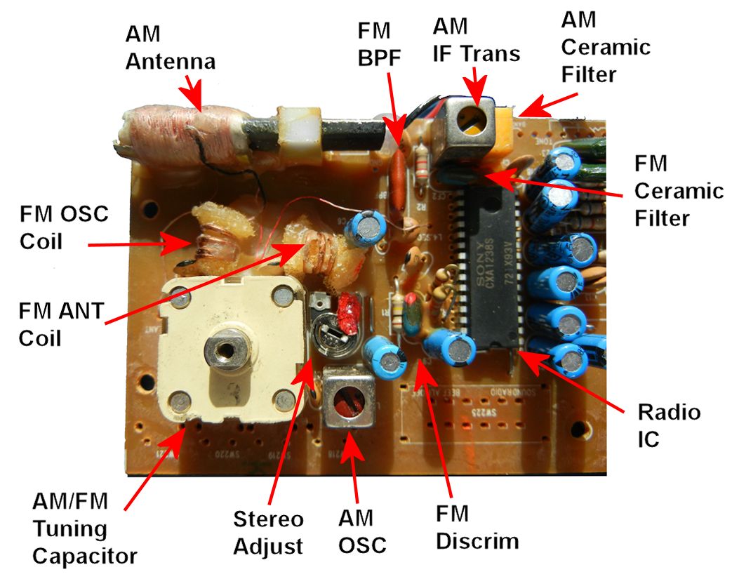
Circuit Board

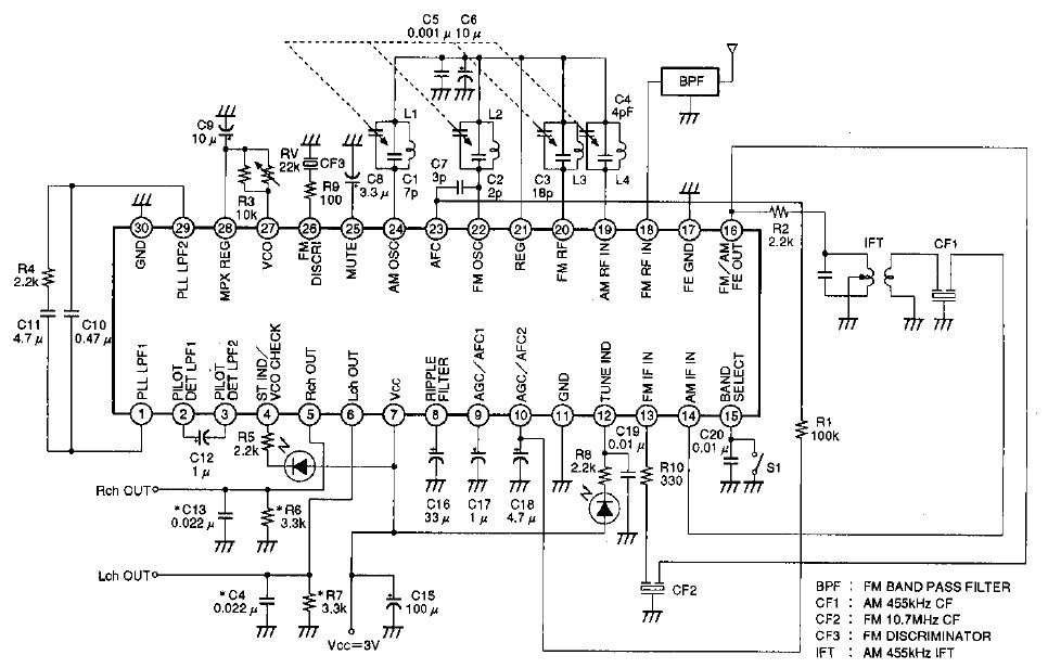
Schematic

Let's go through this one major component at a time.
- Radio IC: This particular radio is based on a Sony CXA1138 IC, an AM / FM stereo IC - which immediately sets it apart from the cheapest radios, many of which do not include FM stereo. Sony, unfortunately, doesn't sell their famous CXA1129 IC to other manufacturers - it is radically better which makes Sony radios some of the best on the market because they deviate substantially from standard superhet architecture. Sony sells a line of conventional superhet IC's to other manufacturers. Sanyo is another very common manufacturer of "radio on chip" IC's.
- Tuning capacitor: Four sections, two devoted to AM, two devoted to FM. This can be replaced by varactor tuning in higher end models, but there is a problem. The voltage generation IC's in digital tuned radios used are not accurate enough to generate the exact steps needed for AM or FM, and varactor diodes are not perfectly linear. This is one of the major reasons inexpensive digitally tuned radios such as iHome are inherently broadband. If they were narrow band, not all stations could be tuned because non-linearities would put them between tuning voltage steps.
- AM ferrite bar antenna: This is fairly standard - and as small as the manufacturer thinks they can get away with. I have seen much smaller - almost so small that the coil completely covers the ferrite bar. The ferrite bar antenna resonates with a section of the tuning capacitor, provided RF to the mixer / oscillator stage. The performance of these radios can be improved to a great degree by simply substituting a larger ferrite bar - provided the case of the radio allows it. A variation of the ferrite bar antenna is a wire formed into a loop on a plastic frame. Unfortunately, most people simply throw these away because they never listen to AM.
- AM oscillator coil: Almost always red core, they resonate with a section of the tuning capacitor to generate the local oscillator frequency, with mixing usually done in the same stage.
- AM IF transformer: The output of the AM mixer produces a 455 kHz intermediate frequency, which is filtered in one or more IF tuned elements. As this is a little higher end radio, it contains two IF elements - a transformer and a ceramic filter.
- AM ceramic filter: This is the most common IF element in radios - usually there is no transformer. These single 455 kHz ceramic filters are usually quite wide in bandwidth - mainly to make tuning easy with a simple tuning mechanism such as a tuning wheel attached directly to the tuning capacitor, or a geared plastic system. The days of large dials and dial string are long gone, the new mechanisms are usually sloppy with a lot of lash. If the radios were narrowband, tuning on frequency would be difficult. If the radio is digitally tuned, the tuning voltage steps are imprecise enough to making tuning to the center of each station almost impossible. Bandwidth of these single ceramic filter elements varies from +/- 10 kHz to +/- 40 kHz. This is a place where a hobbyist can make great improvements in selectivity. Wireless keyboards and mice contain a three stage, stagger-tuned ceramic filter with a bandwidth of +/-6 kHz which can be patched into most radios.
- FM band pass filter: These are more common in walkman style radios where the FM antenna is also the audio return from the headphones. Nevertheless, it is used here probabaly because the FM "antenna" was a length of wire. If by some unhappy circumstance the FM antenna were to short against something else.
- FM Antenna and oscillator coils: These resonate with corresponding sections in the tuning capacitor to tune the FM band. These are usually thick wire coils, held in place with hard wax so the FM radio holds its alignment.
- FM ceramic filter: This is a single 10.7 MHz ceramic filter with a bandwidth of 280 kHz (or greater). There are some significant problems with this approach - the ultmate rejection in the stop band rejection of these filters is only 40 to 50 dB, which means this type of radio can be easily overloaded in the presence of strong signals. It is possible to improve the selectivity of these radios by using 150 kHz ceramic filters, but that does nothing to help the overloading problem without putting more than one filter in series. A 280 kHz ceramic filter is wide enough that the average person can easily tune strong stations. A narrower filter makes the radio harder to tune.
- FM discriminator: This is the FM detector. Usually detection is done with a ceramic discriminator or a transformer.
And - there you have it. The current state of receiver design. Hardly state of the art, but inexpensive, reliable, and suitable for the vast majoritiy of radio users.
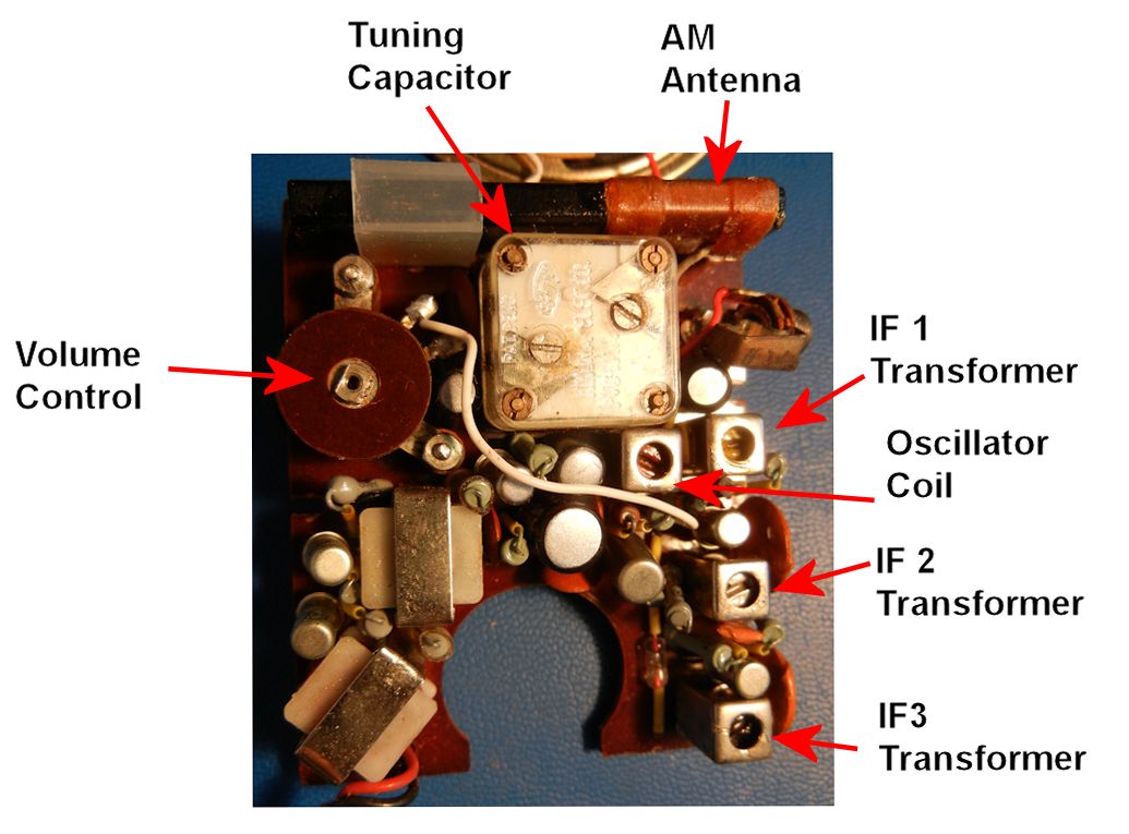
All Japanese 6 Transistor Radio Reference Design
As a comparison, I have attached a picture of an "All Japanese 6" transistor radio, circa 1961. This is what you would find in the majority of radios manufactured prior to 1975, when ceramic filters started making serious inroads:

The three IF transformers made a very selective radio, at the cost of audio bandwidth, which was about 3 to 4 kHz.
As far as I can determine, this design has not been produced in over 30 years.
