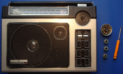
A pictorial guide, hopefully this makes all of your modification and repairs easy. Reverse the instructions to re-assemble.
- Remove four knobs on front by prying off with small screwdriver. The tuning knob will have an associated bushing.
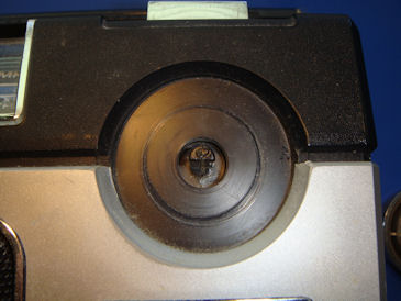
- IMPORTANT STEP – DO NOT SKIP! Turn the tuning shaft until it is positioned as shown, with the flat side facing down towards the bottom of the radio. This will help mitigate the danger of damage to the on/off switch:
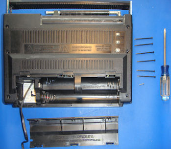
- Remove battery compartment cover and seven case screws, the short one is located in the battery compartment.
- Push the on /off switch to the ON position. CAREFULLY separate the two halves of the clamshell case from the bottom of the unit. It is very easy to damage the on / off switch, so be careful not to apply stress to it.
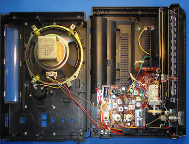
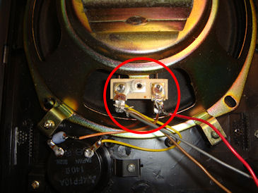
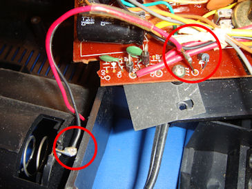
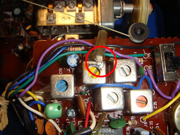
- Unsolder three wires from the speaker. Make a note of which wire goes to which terminal. It is important:
The front of the cabinet is now free. Set it aside on a padded surface to protect it from scratches.
Removing Cabinet Back From Chassis
Note that there may be glue and wax holding wires down, especially antenna and battery wires. You will have to break the wires free to disassemble. Use a hot glue gun if you
want to restore the attachment points. Be careful not to burn the dial string with your soldering iron or you will have to re-string the radio. Not difficult, but an un-necessary hassle if you take a little care.
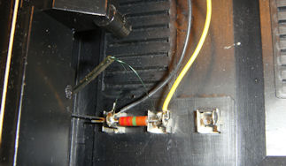
- Unsolder 4 wires from external antenna terminals. Note their positions. Do not use this photo as a reference - this radio actually had a factory mistake! The left green wire should have gone to the right hand terminal. I corrected it when re-assembling.
- Pry off two slide switch knobs and the on/off switch button. Be very careful when prying off the on/off button not to stress the switch. Gently tilting a degree or two while pulling off will help stubborn glue. When re-assembling, you can leave this button off until the cabinet is put back together.
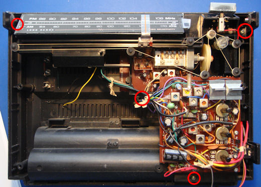
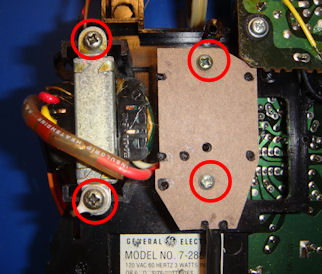
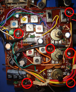
- Remove four chassis screws in indicated positions (the left one was hidden by camera perspective, it is to the left of the dial):
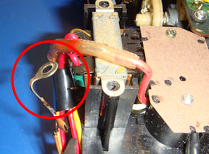
- Move the chassis to expose the black battery compartment wire. Unsolder wires from battery compartment. Remove the positive wire from the battery compartment by sliding back the insulating sleeve and de-solder from the post on the board. Then unsolder the black wire from the battery compartment spring.
The chassis is now free from the bottom half of the case. Place the bottom half of the case aside on a padded surface.
Removing PC Boards From the Chassis
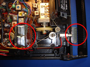
- Turn the chassis assembly over. Unscrew two screws holding the transformer, and two screws holding the power cord retention fiber cover. Note that there is a ground lug on one transformer screw. It is kind of delicate, so be careful not to break the wires on the capacitor.
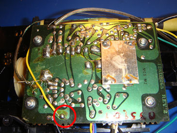
- Remove one screw holding a small PC board that was under the fiber insulator.
The transformer and power cord can now be removed from their molded recessess in the chassis. It is possible that there may be some melting. If so – I recommend NOT using the unit on AC power until the transformer and / or power cord are replaced. Carefully fold the transformer and power cord over to the left away from the chassis.
MANDATORY SAFETY NOTE: If you plan on powering the unit while the transformer is loose like this, raw 115V AC is present on the little miniature two terminal board. Don't come crying to me if you shock yourself!
- Turn the chassis back over. Unsolder the ground strap connecting the two PC boards.
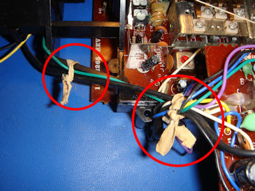
- Remove a couple of tie wraps holding the wire bundle together:
The SR2 circuitry is constructed on two PC boards. You may only need to remove one of the two in order to complete service. You can skip the instructions for the board you don’t need to remove. This might even be preferable, because the front end board, in particular, is very hard to service. The instructions below are not so much removing as loosening so you can get to both sides of the board for service. The radio construction on two boards makes for a lot of interconnection wires, and it is probably better not to disconnect all of them, although you certainly may do so with the excellent diagrams in the manual. But there is little reason to do so, because you can access all the components without doing it, especially with both boards removed from the chassis.
Removing the Main Board
There are just a few steps remaining to loosen the main board, which is much easier to manage than the front end board.
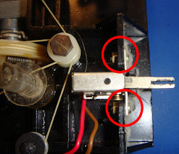
- Unscrew two small screws that hold the power switch to the chassis. There is a nut on the other side, and it is a good idea to use needlenose pliars to help remove the screws and nuts.
- Gently pry the headphone jack miniature PC board from its retaining bracket on the chassis. Don't break anything! It is a pain to get this little board back in the retainer when re-assembling.
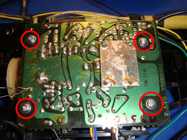
- Remove six screws holding the main board to the chassis.
- The board may now be flipped gently to the left, free of the chassis. Remember that you have the transformer and power cord still connected. A fiber insulator preventing PC board shorts against battery terminals can now be removed as well.
Removing the Front End Board
NOTE: This is a bit more complex. Be prepared to re-string the dial if you mess up. Otherwise, don’t attempt! You have been warned!
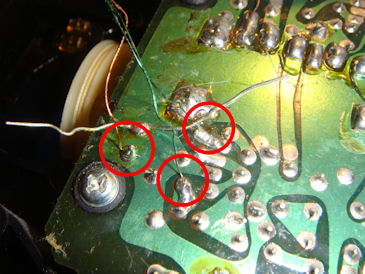
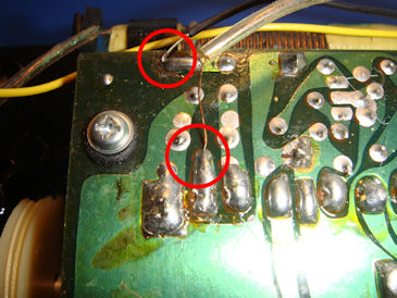
- Unsolder four wires from the AM ferrite rod to the circuit board, and unsolder the FM antenna wires.
- Unscrew four screws securing the front end board to the chassis. Note that these are strain reliefed with rubber, so do not over-tighten when re-assembling.
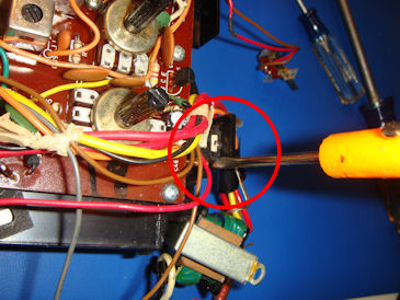
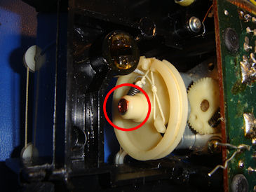
- Gently lift and pull the front end board to the right to gain access to the tuning capacitor pulley retaining screw. You will have to carefully manuever and put a little tension on the dial string to get a screwdriver where you need it. Be careful while unscrewing!
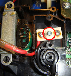
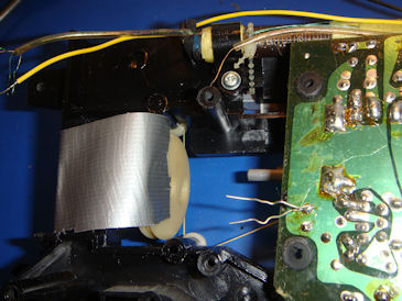
- Secure the pulley with duct tape as shown. Gently slide the tuning capacitor shaft out of the pulley.
The front end board is now loose. It can be removed (with the main board connected) from the chassis.