This page gives you guidance about how to improve the selectivity of just about any FM radio, tuner, or receiver. It assumes that the device is relatively new - manufactured within the last 35 years or so, and is solid state, not tube. That is not to say that you can't use this trick on older radios, but doing so involves a fair bit of electronics know-how, and in the case of tube units there are hazardous voltages that could definitely hurt you. I assume no responsibility if you zap yourself or ruin your radio using the techniques described here. If you don't feel confident working on electronics - don't!
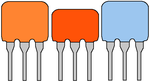
Assuming you are working on a relatively new radio, tuner, or receiver, the first step is to open it up, find the PC board, and look for fingernail sized components known as ceramic filters. For those familiar with electronics, they look like little ceramic disk capacitors, except they have three leads on them instead of two. This is what they look like, although most will be brown:
A simple radio may have one. Most car radios and home stereo components have at least 2 or 3, some may have even more. You must find all of them to get the best results from this article. Close up the radio for now, making a record of where the filters are.
A bit of background before you get started with modifications ---
These ceramic filters are used in the intermediate frequency - or IF circuit of your radio. Consult a web reference on "superheterodyne receiver" if you are unfamiliar with what an IF circuit is. If you are, read on.
Ceramic filters for FM are available in different bandwidths, and the bandwidth probably installed in your radio is 280 kHz. Their center frequency is 10.7 MHz. Since FM stations are spaced every 200 kHz, this means that an optimum ceramic filter bandwidth would be 200 kHz - right? WRONG! FM stations broadcast with a deviation of +/- 75 kHz, and therefore a 150 kHz bandwidth. The bandwidth of the stations frequency deviation is absolutely unrelated to the 200 kHz channel spacing. Which effectively means that the standard 280 kHz ceramic filter bandwidth is almost twice what is really needed to band pass the station. The reason for this is that they are not precise, they can be a little high or low in frequency. Manufacturers do not want to go to the expense of selecting and matching ceramic filters if more than one filter is used. If you use 280 kHz, you are guaranteed of covering the whole station. So selectivity is sacrificed to lower manufacturing costs. But you - as the user - are free to take the time and effort to improve your equipment, and it is relatively easy to do!
The majority of these filters are manufactured by two manufacturers - Murata and Toko, both of which make several bandwidths of these filters. They make 150 kHz ceramic filters, which match the +/- 75 kHz deviation of FM stations. Provided that you match them carefully, you will not have to sacrifice anything - including services in the upper sidebands of the station such as RDS. 150 kHz filters, however, will impact HD sidebands. HD radio is the bane of DX'ers everywhere - if you are after HD reception you should leave the IF section alone - because it requires wider filters to accomodate the sidebands. Most HD radios seem to utiliize a new adaptive IF technology and don't use ceramic filters anyway - or use only one as a broad pre-stage IF filter.
Ceramic filters are becoming more difficult to find, but Digikey has Murata part number SFELF10M7JAA0-B0 / Digikey PN 490-4710-ND. Order several if you have more than one filter, because you will need to match them.
It is better, though, to unsolder the old ceramic filter, clean off the pads, and install the new one flush to the board. Save the old ceramic filters, you may need them later if you have to match filters by trial and error! Clean off the leads.
The best method is to install the new filters in a socket. If you have the right type of IC socket, you can break it down into sections of three pins and install in the ceramic filter location(s). This will be important later for receivers with two or more filters. You have to use the right type of socket, machined pin won't do. It has to have pins with clips that line up horizontally. Here is an example of how to mount ceramic filters in sockets:
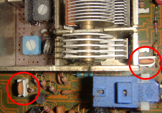
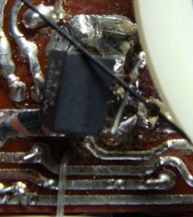
This receiver shows that not all ceramic filters are necessarily lined up in a row. This particular receiver had a third ceramic filter hidden under a bandwidth switch. Rather than deal with soldering and unsoldering that switch to change filters, I just put a filter on the back side of the board. A Pioneer car radio had two ceramic filters where they made sense - on an IF board module. But there was a third hidden - crammed between the RF front end module and the IF module, the only component in a narrow tenth inch gap! A Sony tuner had three ceramic filters neatly in a row, a fourth nearby, but a fifth ceramic filter was across the board - ten inches away from the others! Manufacturers can be tricky!
Mounting filters on the back of a PC board opens up another possibility. Surface mount ceramic filters have pads that are only a little bit wider than tenth inch spacing, and can be mounted on the pads of a through hole version in some cases.
I have to give a mention to Bill Ammons' filter boards. If you need even more selectivity, he sells boards that will replace a single filter with multiple, matched filters. They require a source of external voltage between 11 and 15V because they contain an amplifier that compensates for the cumulative attenuation from multiple filters.
AM radios and tuners can also benefit enormously from the addition of a narrow ceramic filter. Sometimes, it takes a bit of circuit knowledge to know where to put one. These are examples of ceramic filters that have been added to a Radio Shack 12-650 and Radio Shack 12-655:
For more information on ceramic filters, please consult my ceramic filter page.