The GE Superadio (1) Tech Page
The first member of the GE Superadio family was, of course, not labeled "Superadio 1", as the advent of future revisions of the design was not known at the time. The design is about 1970's vintage, and seems to be based on even earlier designs. GE has always produced radio designs that perform well, the addition of tuned RF and additional IF stages was the next logical step.
Another item that made this design possible was the availability of a new "radio on chip"- now available as the NTE1624. It contains the necessary IF and audio gain stages for a conventional AM / FM superheterodyne design. The IC does not have RF gain stages, they are provided in external transistors.


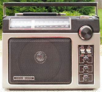
Note that the dial string is not strung properly on a pulley, I corrected that after this photo was taken.
The radio is constructed on 2 boards, a front end board and a main board. These are connected together with several wires, some coax, and one ground strap.


I have written detailed disassembly instructions.
Refer to the graphics below for locations of alignment points. The conventional "coils low" / "caps high" method works well. Don't touch the FM IF and detector unless you know what you are doing. The service manual has the instrument alignment procedure.


I do not recommend retrofitting the original Superadio for the expanded band. I have done it successfully, but there are two problems:
Just about any FM radio can be improved by swapping the stock 280 kHz ceramic filter for a 150 kHz filter. This is certainly the case with the SR1 On the SR1, the capacitor is located by the 1st FM IF can, which is hidden behind the dial scale in the picture above. It is in the upper left of the board. Be careful of the external AM antenna wires, they are fairly small gauge magnet wire. You don't have to worry about matching, there is only one filter. Since this is a mono radio, you can even use a 110 kHz or 90 kHz filter if you have them. I recommend re-installing on the back side of the board, if you choose to that, it is not necessary to completely disassemble and risk having to deal with the dial pulley. It is fairly easy to unsolder the ceramic filter and have it fall off the board, then just tack the new one onto the back of the board.
The mounting for the speaker is the same as for 6 1/2 inch car stereo speakers. You don't want to go crazy with this - the speaker magnet comes very close to the battery compartment so any replacement must have a magnet structure the same size or smaller, and no deeper. Still - budget car stereo speakers that fit those size constraints will fit, and give you better frequency response. I found a suitable pair at Frys for $20 - enough to retrofit two radios.
The GE Superadio and its successor, the GE Superadio 2 are known to have a failure mode where the AM band goes dead, while the FM band continues to work perfectly. This issue has been traced to the band switch. It is large enough and robust enough to allow a good deal of mechanical sheering stress to be applied to the PC board. Over time, this fractures the connection that biases the AM RF transistor. Re-flowing the solder connections near the switch is enough to restore operation in some cases. In other cases, the RF transistor itself is also bad - perhaps the lack of bias damages it. It can be replaced by an NTE229 transistor.
The volume and tone pots, like many pots, have been known to get noisy over time. The picture below shows the most common point of failure, tarnish on the interior portion of the wiper ring, where the tuning fork contact from the pot's middle terminal makes contact:

What I do to repair bad pots.