The GE Superadio 2 Tech Page
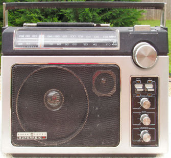
The GE Superadio 2 was a minor variation of the original. Besides cosmetic difference, the only real change was the addition of a tweeter. This causes the 10 kHz heterodyne whine to be more pronounced on the "2".
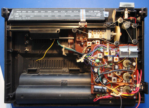
The radio is constructed on 2 boards, a front end board and a main board. These are connected together with several wires, some coax, and one ground strap.


The existing Thompson manual schematic I found on the web is terrible. I have transcribed it the best I can using OrCad Capture. There was conflicting and missing information on the original, which I resolved the best I could as an experienced Engineer. I found it particularly hard to discern every "dot" where wires crossed. If you can find any mistakes - PLEASE let me know about them!
The radio is constructed on 2 boards. If you prefer to look at the schematic that way, here it is:
The circuit partitioning on those schematics is not the best for understanding functionality. For your convenience (and schematic readability), I have split it into several functional sections:
Internet Explorer fits the graphic to the screen on low screen resolutions. If the schematic is unreadable, be sure to click that zoom thing in the lower right hand corner. Or just right click the graphic to download.
I have written detailed disassembly instructions.
Refer to the graphics above for locations of alignment points. The conventional "coils low" / "caps high" method works well. Don't touch the FM IF and detector unless you know what you are doing. The service manual has the instrument alignment procedure.


The AM band was expanded to 1700 kHz after the SR2 was manufactured. Fortunately, this is still well within the range of alignment. All that is required is to align the radio with 1700 as the top frequency. This will, of course, make the dial inaccurate for AM. I have solved this for you. I scanned the existing dial, and altered the AM side with Paint Shop Pro to make a new dial. The artwork is below, feel free to snag the graphic:

The graphic is actually really BIG, you will have to scale it to fit the radio. I made it really big so small mistakes would disappear when reduced. Except for the fact that now you won't have the cool reflective strip, the new dial legend can be glued directly over the old, and your SR2 will look like it was manufactured for the expanded band.
Just about any FM radio can be improved by swapping the stock 280 kHz ceramic filter for a 150 kHz filter. This is certainly the case with the SR2 On the SR2, the capacitor is located by the 1st FM IF can, which is hidden behind the dial scale in the picture above. It is in the upper left of the board. Be careful of the external AM antenna wires, they are fairly small gauge magnet wire. You don't have to worry about matching, there is only one filter. Since this is a mono radio, you can even use a 110 kHz or 90 kHz filter if you have them.
The GE Superadio 2 and its predecessor, the GE Superadio are known to have a failure mode where the AM band goes dead, while the FM band continues to work perfectly. This issue has been traced to the band switch. It is large enough and robust enough to allow a good deal of mechanical sheering stress to be applied to the PC board. Over time, this fractures the connection that biases the AM RF transistor. Re-flowing the solder connections near the switch is enough to restore operation in some cases. In other cases, the RF transistor itself is also bad - perhaps the lack of bias damages it. It can be replaced by an NTE229 transistor.
The volume and tone pots, like many pots, have been known to get noisy over time. The picture below shows the most common point of failure, tarnish on the interior portion of the wiper ring, where the tuning fork contact from the pot's middle terminal makes contact:

What I do to repair bad pots.