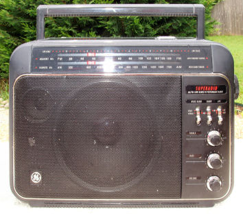
The GE Superadio 3 presented a radical departure from the previous two models. The cabinet was completely redesigned, the tuning capacitor was replaced by varactor tuning, and a bandwidth switch was added on AM.
Here is the stuff you probably came here for:
That's what I come here for myself! And I was always having to look for it. No more!
The rest of the stuff and other fixes are below ----
There are two versions of the main board - one with a discrete FM front end, and one that is IC based.


The existing Thompson manual schematic I found on the web is terrible. I have transcribed it the best I can using OrCad Capture. There was conflicting and missing information on the original, which I resolved the best I could as an experienced Engineer. I found it particularly hard to discern every "dot" where wires crossed. If you can find any mistakes - PLEASE let me know about them!
For your convenience (and schematic readability), I have split it into several functional sections:
Internet Explorer fits the graphic to the screen on low screen resolutions. If the schematic is unreadable, be sure to click that zoom thing in the lower right hand corner. Or just right click the graphic to download.
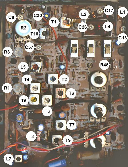
Refer to the graphic below for locations of alignment points. The conventional "coils low" / "caps high" method works well. Don't touch the FM IF and detector unless you know what you are doing. The DC-DC converter coil doesn't need to be adjusted at all if you can tune to the high end of both bands. Don't touch the Tune Low and Tune High pots unless your radio is off by the same amount on both bands. Consult the Thompson Service Manual if you want step by step instructions. If you use the manual, several other people have done diagrams of parts with reference designators.
The SR-3 has a problem that older SR's don't have. The tuning scale is on the exterior of the case. This makes alignment really difficult, because you don't have access to the scale. I have a solution to the problem - I made a copy of the dial, only in negative image on my printer. Before taking the radio apart, I tune to a known frequency and am careful not to move the tuning while I take the knobs off and disassemble. I then tape the dial onto the black plastic and presto - I have numbers that I can use to do alignment! I would put a graphic here, but modern "all in one" printer scanners make this so easy to do I won't bother. And a more serious reason is that there are TWO different scales, and the numbers are distributed differently. Use the wrong one, and your alignment could be way off.
Some of these mods can be done without disassembling the PC board - from the top of the board. The first few of these are in this category, and the pictures show this approach. With the advent of the fix for the tuning pot, I usually just take the board out and do all of these at once. But I'll show this old way in case some of you are lucky enough to have early production SR3's that don't need the complex tuning pot fix.
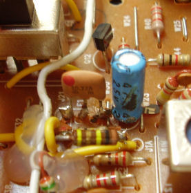
The Q of the antenna circuit can be increased by decreasing the value of R7. R7 comes stock - at least on early production units - at 100k. Changing it to 47k helps - I usually just put another 100k in parallel:

I have tried as low as 33k - it gets unstable, starting at the high end of the band. If you experience it - back off the resistor value.
This is caused - as near as I can tell, by the base current of Q14 being starved by R10 being too large. R10 comes stock - at least on early production units - at 100k. Changing it to 47k helps - I usually just put another 100k in parallel:

Later production units (sometimes) have this change already made. Some batches of Q14 are fine with 100k, others need the change. Experiment a bit and you will get it right.
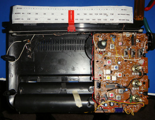
The GE Superadio 3 can benefit from a narrow ceramic filter the same as any other FM radio. Referring to the picture above - the ceramic filter is near the center of the board. The radio comes with a 280 kHz filter installed, any width down to 90 kHz should work.
When I do this mod from the top of the board, I clip out the old ceramic filter:

Then I solder onto the stubs of the old leads:
Of course, if you have the board loose, you can either solder the new IC to the board, or use a socket for the filter.
The GE Superadio 3 has some pretty small output coupling caps on the audio. Bass response can be improved by increasing C58 and C59 from 470uF to larger values, however there is not a lot of vertical space above the board. It may be necessary to locate these caps somewhere else, possibly by the battery compartment, and wire over to the PC board.
I only have the service manual for the discrete transistor FM front end version. If you have the manual for the IC front end version, I would be very grateful if you could send me scans or a .pdf!
The schematic is much improved from my previous efforts, due to advances in graphics programs such as 0.01 degree rotation increments, the ability to make tiny adjustments in fuzziness to even out lines, etc. If I ever get the chance to scan the schematic myself, I promise to post an improved version. But for now, this is the best I could do off of the scans existing on the internet now. It was the result of many hours of work to get things lined up properly and readable all over. Feel free to snag the graphic to do any print operations you need to do.