As it came out of the box, the 12-603 is not even close to GE Superadio performance. It is certainly a good performer, but some compromises were made to reduce cost. Fortunately, many of these compromises can be reversed. When modified with the modications below, it comes very close to Superadio performance. In fact, given that this radio has a more stable tuning pot than the Superadio 3, an experienced hobbyist might do well to consider purchasing this radio off of eBay, when available, instead of a Superadio 3 of unknown stability.
You should start by printing out a copy of my 12-603 Disassembly page. This will allow you full access to the PCB, which is essential for most of these modifications.
If you don't feel confident in doing these modifications, I can do them for a nominal fee. Contact me at the Superadio III Yahoo group.
The single most important modification that you can do is to install a better ferrite bar in the radio. In fact, this holds true for just about any radio - the ferrite bar should be as large as the case will allow.
The 12-603 has a 120 mm (4 3/4 inch) ferrite rod antenna for AM reception instead of 200 mm (7 7/8 inch) in the GE. The 12-603 uses the cavity behind the dial scale to hold the ferrite rod, and the cavity is large enough for a 200mm ferrite bar:
Some extra support for the ferrite bar is advisable if the radio will be subject to frequent jarring - possibly using the on/off switch screws as a starting place for additional support. Sensitivity is almost as good as the GE SR-3 with the new ferrite bar. Substituting a longer ferrite rod in the 12-603 is a bit tricky - but the disassembly instructions should help.
FM performance can be improved by substituting a 150 kHz ceramic filter (see bottom left corner of the IC) for the stock 280 kHz ceramic filter:
"On AM the radio uses a tuned RF section. Interestingly, the AM IF filtering only uses two IF-cans. Probably the designers thought that with the tuned RF section it is enough. Adding a ceramic filter between the coils, as other AM ICs do, could be a possible modification. I have not used much my radio on AM to really comment on the lack or adequacy of the selectivity." - Peter
The two AM IF transformers are the ones with yellow cores in the picture above. I took Peter's suggestion and found that the right place to insert an AM ceramic filter is to substitute it for C115:

I used a ceramic filter out of an old wireless keyboard / mouse combo. These are three element stagger tuned ceramic filters with a bandwidth of +/- 6 kHz, which won't make the radio selective enough for Trans-Atlantic splits, but the stop band response is excellent - just what this particular radio needs most. I mounted the filter upside down "dead-bug" style. The input and output pins are along one side, and three ground connections along the other. A nearby transformer case made a convenient ground connection, and old component leads made the connection to the pads where C115 had been.
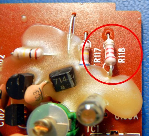
"The AM osc. coil is shunted by a 2.2KOhm resistor, R118, which is not needed. In fact, it totally ruins the Q of the osc. circuit. Low Q also ruins the stability of an oscillator! The LA1260 IC uses an osc. level control circuit, if the designers thought that R118 will limit osc. level variation with tuning. The application example does not use that resistor in the datasheet. I disconnected that resistor." - Peter
The resistor in question is in the corner of the PC board as shown below:

"The circuit uses careful filtering of the Vcc to the RF and IF ICs on the stabilized 5V supply. In fact, one of the filter resistors, R121, 100Ohm, to the LA1260 IC, is excessive. The voltage on pin 6 drops down to about 3.2V. The performance parameters are given at 4.5V Vcc, the operating limit is 3V, and the parameters start to deteriorate as Vcc approaches 3V. I changed that resistor to 22Ohm, now Vcc on that pin is 4.6/4.8V (FM/AM)." - Peter

The photograph shows the resistor already changed. I also circled the position of the nearby FM ceramic filter that was changed in a previous step.
"I also added a tuning indicator LED to pin 7, the IC drives that through an external 1K resistor. I mounted a small LED into the end of the tuning scale back panel. It looks good." - Peter
Actually doing this requires a bit of thought, so I'll detail how I did it.
First, I punched a hole in the dial scale on the right hand side for the LED. I use a heat punch (a soldering iron tip that lost its plating a long time ago) to put a hole near where the dial scale ends, and where the tuning indicator LED would not interfere with the longer ferrite rod I installed. I quickly realized I would also need a second hole to get wires from the PC board out to the LED:

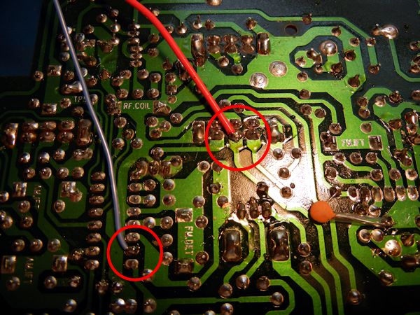
Next, I needed to figure out the right places to attach the wires for the LED to the PC board. One wire, of course, goes to pin 7 of the LA1260. The other wire, of course, needs to go to +5V. I found a convenient connection on the middle of one row of the band switch:

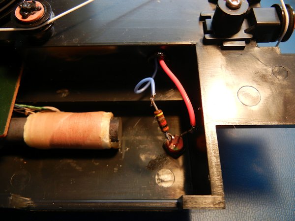
Finally, I connected the wires to the LED and current dropping resistor in the cavity behind the dial:

I show the connections before I added sleeving to keep the connections from shorting. My take on the tuning indicator - I was expecting more of an analog type of function with the brightness of the LED being a guide to when I was approaching the center of the channel. What it actually does, however, is more digital in nature - when you are tuned properly it suddenly turns on, and turns off when you go off channel. I note that it turns on even with fairly weak signals. The 12-603 is one of the few radios I own that will pick up very weak KMVL Madisonville TX on 1220, next to local KQUE 1230. But the tuning indicator comes on full intensity for KMVL, turns off as I tune to the right, then comes back on again for KQUE. Neat!
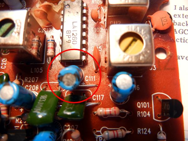
"The datasheet suggests to use 10uF capacitor for the AGC delay, the radio originally uses 22uF (C111), this also delays the on/off action of the tuning indicator." - Peter
The photograph shows the location of this capacitor:

I actually did this mod before the AM ceramic filter mod above, to make access to the capacitor easier. The AGC time constant was one of my pet-peeves about the radio, it always was sluggish in responding to big changes in signal strength as I tuned across the band. This definitely makes it better.
I am left with a really good, servicable Superadio clone. It is definitely more stable than even an SR-3 with a good tuning pot. Side-by-side sensitivity with GE SR3 shows similar AM sensitivity, perhaps better AM selectivity. I haven't said a lot about FM, I really can't tell much difference between the SR3 and the 12-603, but the 12-603 may actually be better. The only negative I still have with the radio is that the AVC runs out of room on weak stations, you have to turn the volue way up, which means weak stations will be hard to hear in high ambient noise situations. It also is annoying tuning across the band, you can get a very loud local after tuning a weak distant station. Perhaps Peter or some other contributor can come up with a fix for this as well. We do have a "cheat sheet" of sorts - the CCrane radio EP also uses an LA1260 and does not have the AVC issue, so if we can get a schematic of it and compare the two, a fix may be obvious. Dial calibration is not great, but better than an SR-3, especially an SR-3 modified to have a better tuning pot. If you see one of these on eBay and can do the modes - grab it!