Realistic 12-675 "Frankenradio"

This page will be different from the other tech pages on this site. It is a restoration project of an old classic.
I came across a sad remnant in my attic the other day. It is the PC board out of a classic DX radio from around 1970 - the Realistic (Radio Shack) 12-675.

This radio has some sentimental value to me - it is the one that I used for serious AM DX of all the famous AM top-40 stations - WABC, WLS, etc. All great stations that are gone now, but can the radio I used 40 years ago be saved? Over time, moisture had destroyed much of the case, rust attacked the polished metal, and decades ago I deemed the radio a total loss, discarding the case, saving only the PC board. I now know that was a mistake. No matter how bad the case was, I should have preserved the radio.
A look at eBay revealed no 12-675's - not even badly deteriorated units - for sale. So I am left with a radio without a case, a naked PC board. But - as resident GE Superadio expert - I have extra cases and hardware designed for the GE SR-3. Could I somehow use an SR-3 case and make a usable radio?
Update on this story: I found a on eBay, and have done a restoration on it. Because its PC board was much better than my original, I decided not to do a "transplant". You can now go to my 12-675 Technical Page if you want good technical information on this radio.
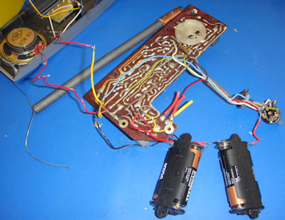
I next looked in my part bins to find as many of the original 12-675 parts as possible. I located the original ferrite bar and the battery holder, but neither was suitable for use in my new hybrid. I have a case large enough for a 200 mm ferrite bar, instead of the original which is half that length. The battery holder holds four C batteries in a row, which would be too long to fit in the SR3 battery compartment. I bought two Radio Shack side-by-side C battery holders to use instead.
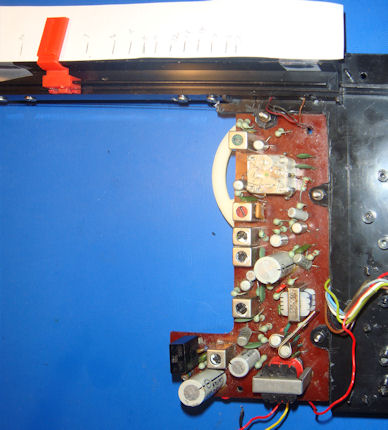
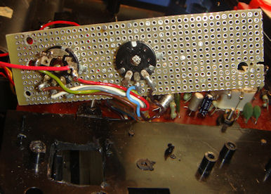
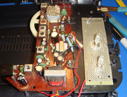
The front and rear PC boards are shown below:
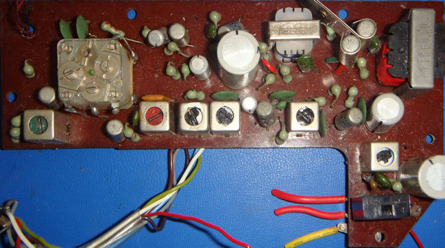

I notice I had already done extensive modifications to the board, I have no idea what my rationalization was. I literally loved this radio almost to death! The layout of the board is very clean and open, the RF section to the left, then the converter oscillator to the right of the tuning cap, then the four IF stages. Audio is above the IFs, power input on the lower left. It utilizes eight transistors of a very archaic type.
Time to get busy and see if this board can still work! I hooked up power, a speaker, installed a ferrite bar, and found a temporary dial pulley.
I rotated the on/off volume switch to turn the board on and - nothing happened. My heart sank - I wanted so badly for this to work! But wait, tuning across the band, I noticed some very faint audio from strong local stations. Suspecting the problem - I rotated the volume knob and - locals punched through very loudly, and more distant stations were all there, too, even without moving the ferrite bar. It's - ALIVE!
Before doing anything else, I disassembled that volume control. As I suspected - it was filty and the metal contacts tarnished:
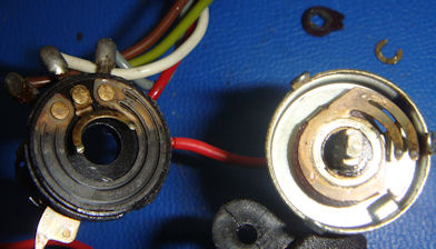
I have a tried and true regime for fixing pots like this. This one is pretty badly worn but I should be able to get a little more use out of it. I first clean everything, especially the carbon element with a paper towel to get years of carbon shavings and gunk out. Next, I use a pink eraser to clean the metal parts, the fork coming off the center terminal, the points that make contact with the carbon element, but especially the ring where the fork contacts the moving metal contact. The point of the eraser needs to be sharp to get in there. Only a couple of light wipes are needed! Don't overdo it, even though the pink eraser is about the lightest abrasive most people have access to. It is very easy to lose plating that you don't want to lose! Everything shiny:
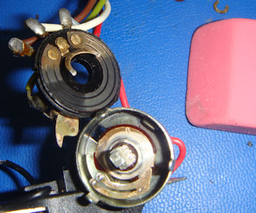
Finally, I do something controversial - but it works. I put a very thin coating of synthetic wheel bearing grease on the moving parts. The carbon, the spring contacts, etc. I bend the contacts on the fork and moving element ever so slightly in case there is spring fatigue, and re-assemble. I can forget that problem - it will never happen again, at least not in my lifetime! I have pots and switches I treated over 30 years ago that are just as smooth and problem free as the day I fixed them.
With the pot fixed, I did a quickie alignment and band scan. It easy covers the expanded band, but the antenna trimmer was very noisy! Fortunately once set it isn't noisy. The radio was badly out of alignment, but once it was aligned, it is very clearly a good DX board. How good will have to wait until I get my Frankenstein monster completed and do a really good alignment.
I have to start somewhere, so I started at the antenna. I know from past experience that I will need to punch a couple of holes in the plastic chassis to connect the antenna to the board. That done, I unsoldered the antenna coil from the board and installed the wires through the holes:
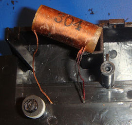
Next, I installed the ferrite bar. I didn't have any of the nice clips that GE uses to mount the ferrite bar, but the original 12-675 mounts do almost as well:
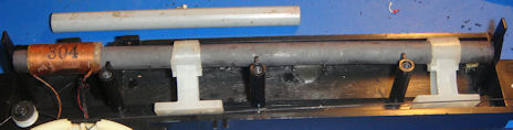
Notice the original ferrite bar with its distinctive gray shrink wrap coating above the new one. That is as close as it will ever get to being used again in this radio! Bye bye mediocre - hello good antenna!
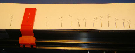
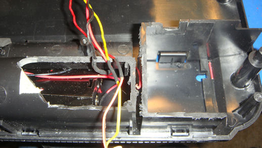
The GE SR chassis needed extensive work to hold the 12-675 board. I opted for hollowing out the chassis in the entire area where the board would be located, so I could do a bottom mount. I primarily did this to line up the dial pulley with the idler wheels already on the chassis for dial string. As far as I know, I did locate the original dial pulley. So if I really wanted, I could probably scale a graphic of the original dial from the picture above to work with the radio. But there is the matter of the new expanded band alignment, so I abandoned the idea.
I had to pry off the ground plate, take off the AC strain relief on the rear, remove several posts and screw supports. I then used the board as a template for marking the chassis - with the location of the tuning pulley pretty much dictating where the board would go. I was very careful to leave mounting tabs for the screws that would support the board in its new chassis. This is the result:
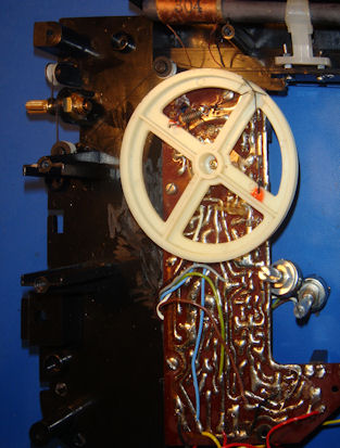
I soldered the antenna wires back to the board, and then installed the dial pulley. I strung the dial with rug thread, using the concept from the SR-3 dial cord stringing. I then installed the pointer, taped some paper onto the SR-3 scale area, and marking the new tuning scale:
A quick check showed me that the new dial scale was not as long as the GE - darn! I had hoped that maybe I could just use the numbers already printed there. No such luck - I'll have to tape something on top of the GE scale.
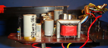
When doing a project like this, you always have to keep the end objective in mind. In this case, a usable portable radio. But as the board was mounted, there were components - mainly caps - that were too tall to allow the top cover to be used:
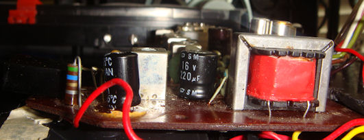
Not a problem at all - I have a good stock of more recent aluminum electrolytic caps manufactured after the drying out problems of the 60's and 70's had been solved. I usually am against shotgun replacement of caps unless there is a good reason, but I had one. The audio sounds a bit distorted. Not bad - but definitely distorted. I'll need to track that down at some point and fix it, but bad caps is a great place to start. After re-capping, I also laid a dual diode package on the left horizontal. It is hard to see with black on black:
Darn! The audio is still distorted. I've got a bad transistor in the audio stage somewhere. That will be hard to replace. But the audio isn't too bad, so I'll continue with the restoration.
These required a bit more work on the chassis and the fabrication of a board to hold them. My first impulse was to get out the hot glue gun again, but the on/off switch mechanism made that impractical, hence the board. After that, it was a matter of finding the right spacers to put the control shafts at the correct height for the knobs:
I knew about this from when I mounted the board on the chassis, but now was the time to deal with it. The left part of the board extends over the battery compartment, and the battery compartment is at least 1/4 inch too high. I needed to do extensive machining of the compartment so the board / chassis combination would fit:
Problem solved, all that remained was for me to hook up the battery holders to the board:
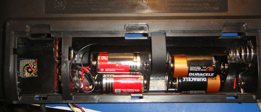
Yes, I know I mixed battery types. I then soldered the speaker wires, and assembled the radio. A bit of artwork for the dial to make it nice, tape it down, and the finished radio was ready to go:
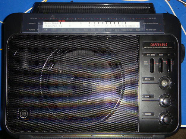
It is definitely not up to SR(1) standards, but is a very good DX radio. The tuned RF stage really gives it a boost over non-tuned RF stage models. The selectivity is not as good as an SR(1), it is about SR3 standards, maybe a bit better. This will definitely be a conversation piece, but until I track down the audio problem it doesn't sound very good.